EMC REVERBERATION CHAMBERS
A reverberation chamber (MSRC) is a metallic cavity fitted with a
mode stirrer; the resonances of the cavity are modified in a random
fashion by mode stirring in order to obtain a field that is considered
statistically uniform. Reverberation chambers allow to produce high
fields, up to several hundreds or thousands of V/m, with optimized
input power. They illuminate the equipment under test (EUT) with
isotropic radiation.
OPERATING PRINCIPLE
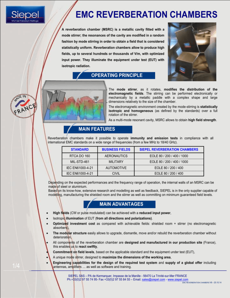
The mode stirrer, as it rotates, modifies the distribution of the
electromagnetic fields. The stirring can be performed electronically or
mechanically by a metallic paddle with a complex shape and large
dimensions relatively to the size of the chamber.
The electromagnetic environment created by the mode-stirring is statistically
isotropic and homogeneous (as defined by the standards) over a full
rotation of the stirrer.
As a multi-mode resonant cavity, MSRC allows to obtain high field strength.
MAIN FEATURES
Reverberation chambers make it possible to operate immunity and emission tests in compliance with all
international EMC standards on a wide range of frequencies (from a few MHz to 18/40 GHz).
STANDARD
BUSINESS FIELDS
SIEPEL REVERBERATION CHAMBERS
RTCA DO 160
AERONAUTICS
EOLE 80 / 200 / 400 / 1000
MIL-STD-461
MILITARY
EOLE 80 / 200 / 400 / 1000
IEC EN61000-4-21
AUTOMOTIVE
EOLE 80 / 200 / 400
IEC EN61000-4-21
CIVIL
EOLE 80 / 200 / 400
Depending on the expected performances and the frequency range of operation, the internal walls of an MSRC can be
made of steel or aluminium.
Based on its know-how, extensive research and modelling as well as feedback, SIEPEL is in the only supplier capable of
modelling, manufacturing the shielded room and the stirrer as well as committing on minimum guaranteed field levels.
MAIN ADVANTAGES
1/4
High fields (CW or pulse modulated) can be achieved with a reduced input power,
Isotropic illumination of EUT (from all directions and polarizations).
Optimized investment cost as compared with achievable fields: shielded room + stirrer (no electromagnetic
absorbers),
The modular structure easily allows to upgrade, dismantle, move and/or rebuild the reverberation chamber without
deterioration,
All components of the reverberation chamber are designed and manufactured in our production site (France),
this enables us to react swiftly,
Commitment on field levels, based on the applicable standard and the equipment under test (EUT),
A unique mode stirrer, designed to maximize the dimensions of the working area,
Engineering capabilities for the design of the required test system and supply of a global offer including
antennas, amplifiers … as well as software and training.
SIEPEL SAS – PA de Kermarquer, Impasse de la Manille - 56470 La Trinité-sur-Mer FRANCE
Ph.+33(0)2 97 55 74 95- Fax +33(0)2 97 55 84 55 – Email: sales@siepel.com - www.siepel.com
EMC REVERBERATION CHAMBERS V6 – 20.10.14
EMC REVERBERATION CHAMBERS
DIMENSIONS vs FREQUENCIES
Large reverberation chambers enable to work at low frequencies while ensuring attractive minimum normalized
field levels.
Small reverberation chambers are used in full compliance at high frequencies with the highest normalized field
levels.
The choice of reverberation chamber will therefore be a trade-off between three main criteria:
The Equipment under test (EUT) dimensions,
Frequency range of operation,
Power level available and field strength required.
Current standard models of reverberation chambers are characterized by their lowest usable frequency (LUF)
SIEPEL STANDARD MODELS*
Lowest Usable
Frequency (LUF)
Working volume
EOLE 80
EOLE 200
EOLE 400
EOLE 1000
≥ 80 MHz
≥ 200 MHz
≥ 400 MHz
≥ 1000 MHz
4.10 x 3.30 x 2.00 m 2.72 x 1.69 x 2.11 m 2.66 x 1.25 x 1.36 m 0.72 x 0.56 x 0.40 m
External dimensions
(incl. stiffeners)
9.51 x 6.80 x 5.40 m 4.88 x 3.76 x 3.23 m 3.45 x 2.52 x 2.90 m 1.02 x 0.86 x 1.28 m
Internal dimensions
9.30 x 6.10 x 4.96 m 4.84 x 3.72 x 3.11 m 3.41 x 2.48 x 2.86 m 0.98 x 0.82 x 1.24 m
*Customized models available upon request (for larger EUT size, other LUF …)
EOLE 80
EOLE 200
EOLE 400
EOLE 1000
See real dimensions for each model in the table above
2/4
SIEPEL SAS – PA de Kermarquer, Impasse de la Manille - 56470 La Trinité-sur-Mer FRANCE
Ph.+33(0)2 97 55 74 95- Fax +33(0)2 97 55 84 55 – Email: sales@siepel.com - www.siepel.com
EMC REVERBERATION CHAMBERS V6 – 20.10.14
EMC REVERBERATION CHAMBERS
NORMALIZED FIELDS
Following normalized E fields are achievable with 1 watt input power.
These values have to be considered for an empty chamber: coaxial or waveguide loss not included
Galvanized steel EOLE 80
DO160 standard
According to:
IEC/EN61000-4-21 and MILSTD461F standards
Galvanized steel EOLE 200
According to:
DO160 standard
IEC/EN61000-4-21 and MILSTD461F standards
Aluminium EOLE 400
DO160 standard
According to:
IEC/EN61000-4-21 and MILSTD461F standards
Aluminium EOLE 1000
DO160 standard
According to:
IEC/EN61000-4-21 and MILSTD461F standards
3/4
SIEPEL SAS – PA de Kermarquer, Impasse de la Manille - 56470 La Trinité-sur-Mer FRANCE
Ph.+33(0)2 97 55 74 95- Fax +33(0)2 97 55 84 55 – Email: sales@siepel.com - www.siepel.com
EMC REVERBERATION CHAMBERS V6 – 20.10.14
EMC REVERBERATION CHAMBERS
TURNKEY SYSTEM
SIEPEL provides complete test system inclusive of Reverb Chamber, software, RF
instrumentation (amplifiers, antennas …), on-site set-up and user training.
Based on the customer inputs (applicable standard, LUF, EUT dimensions, available
instrumentation), SIEPEL can define the test facility as a whole and determine the
required output power of the amplifiers, taking into account the losses from
coaxial cables, harmonic filters, etc.
MEASUREMENT SOFTWARE
All rights reserved. Information presented in this document are subject to modifications
The key element when performing EMC tests in Reverb Chamber is the use of a
proper software package.
SIEPEL offers the most user-friendly, comprehensive solution, which has been
approved and used by many international labs. It integrates various modules that
enable, among other, to perform following tests:
Radiated immunity measurements in reverb chamber (EMS/CHR)
Emission measurements in reverb chamber (EMI)
This software allows to carry out full-compliance measurements in reverb chambers
according to EN61000-4-21, RTCA DO 160, MIL STD standards as well as for custom
applications.
If you need further information about Reverb Chambers, please do not hesitate to ask for
your personal copy of our “Mode-Stirred Reverberation Chambers reference guide”
“Everything you ever wanted to know about reverberation chambers but never dared to ask!”
Please contact Mrs Stéphanie JÉGAT: s.jegat@siepel.com.
4/4
These data are the result of tests performed in our laboratory. The use of the material and the performance specifications are
the entire responsibility of the users who should ensure that the material is suitable for their purposes
SIEPEL SAS – PA de Kermarquer, Impasse de la Manille - 56470 La Trinité-sur-Mer FRANCE
Ph.+33(0)2 97 55 74 95- Fax +33(0)2 97 55 84 55 – Email: sales@siepel.com - www.siepel.com
EMC REVERBERATION CHAMBERS V6 – 20.10.14

