Sustainable solutions
PowerSafe TS
®
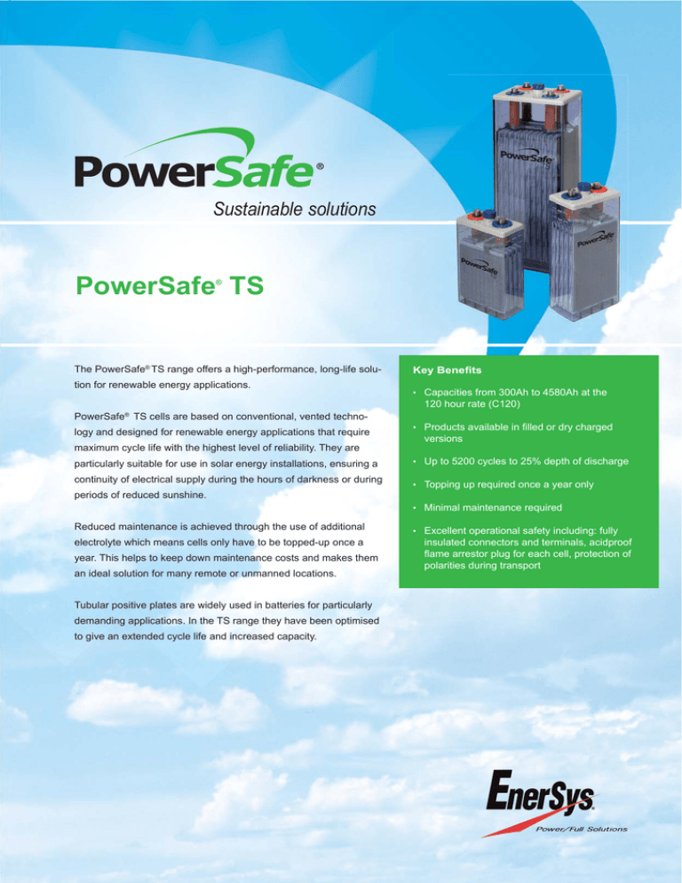
The PowerSafe® TS range offers a high-performance, long-life solution for renewable energy applications.
Key Benefits
• Capacities from 300Ah to 4580Ah at the
120 hour rate (C120)
PowerSafe® TS cells are based on conventional, vented technology and designed for renewable energy applications that require
maximum cycle life with the highest level of reliability. They are
particularly suitable for use in solar energy installations, ensuring a
continuity of electrical supply during the hours of darkness or during
periods of reduced sunshine.
• Products available in filled or dry charged
versions
• Up to 5200 cycles to 25% depth of discharge
• Topping up required once a year only
• Minimal maintenance required
Reduced maintenance is achieved through the use of additional
electrolyte which means cells only have to be topped-up once a
year. This helps to keep down maintenance costs and makes them
an ideal solution for many remote or unmanned locations.
Tubular positive plates are widely used in batteries for particularly
demanding applications. In the TS range they have been optimised
to give an extended cycle life and increased capacity.
• Excellent operational safety including: fully
insulated connectors and terminals, acidproof
flame arrestor plug for each cell, protection of
polarities during transport
2
Range Summary > PowerSafe® TS <
General Specifications
Type
Nominal
Capacity (Ah)
Nominal Number 10 hr rate
Voltage
of
to
(V)
Termi1.80Vpc
nals
@20°C
120 hr rate
to
1.85Vpc
@25°C
Nominal Dimensions
Length
mm
in
Width
mm
in
Height
mm
in
Typical
Weight Dry
charged
kg
lbs
Typical
Weight Acid
Filled
kg
lbs
Electrolyte Short Internal
Volume
Circuit
ResiLitres US Current stance
Gal
(A)
(mΩ)
TLS 4
2
2
220
300
103
4.06
206 8.12
389
15.33
13.0
28.6
18.0
39.8
3.9
1.0
2059
1.02
TLS 5
2
2
270
367
124
4.89
206 8.12
389
15.33
15.5
34.2
21.9
48.2
4.9
1.3
2625
0.8
TLS 6
2
2
323
440
145
5.71
206 8.12
389
15.33
18.1
39.8
25.6
56.5
5.8
1.5
3000
0.7
TVS 4
2
2
340
460
124
4.89
206 8.12
505
19.9
18.4
40.6
27.3
60.3
6.9
1.8
2838
0.74
TVS 5
2
2
390
530
124
4.89
206 8.12
505
19.9
21.5
47.3
30.0
66.2
6.6
1.7
3281
0.64
TVS 6
2
2
470
640
145
5.71
206 8.12
505
19.9
25.1
55.3
35.4
78.0
7.9
2.1
3750
0.56
TVS 7
2
2
550
745
166
6.54
206 8.12
505
19.9
28.7
63.2
40.7
89.7
9.2
2.4
4200
0.5
TYS 5
2
2
590
802
145
5.71
206 8.12
684
26.95
29.8
65.8
44.6
98.3
11.3
3.0
3621
0.58
TYS 6
2
2
670
912
145
5.71
206 8.12
684
26.95
34.0
75.0
48.4
106.7
11.0
2.9
4200
0.5
TYS 7
2
2
816
1120
191
7.53
210 8.27
684
26.95
40.5
89.2
59.6
131.3
14.8
3.9
5147
0.41
TYS 8
2
2
900
1220
191
7.53
210 8.27
684
26.95
44.6
98.4
63.2
139.4
14.5
3.8
5676
0.37
0.32
TYS 9
2
2
1040
1415
233
9.18
210 8.27
684
26.95
50.2
110.8
73.9
163.0
18.3
4.8
6625
TYS 10
2
2
1120
1523
233
9.18
210 8.27
684
26.95
54.4
119.9
77.8
171.6
18.0
4.8
7000
0.3
TYS 11
2
2
1260
1714
275
10.84 210 8.27
684
26.95
60.0
132.2
88.4
194.8
21.9
5.8
8108
0.26
TYS 12
2
2
1340
1825
275
10.84 210 8.27
684
26.95
64.1
141.4
92.3
203.5
21.6
5.7
8824
0.24
TZS 11
2
4
1560
2130
275
10.84 210 8.27
829
32.66
76.5
168.6 112.3 247.6
27.5
7.3
7554
0.28
TZS 12
2
4
1710
2335
275
10.84 210 8.27
829
32.66
81.7
180.0 117.0 257.9
27.1
7.2
8400
0.25
TZS 13
2
6
1940
2640
399
15.72 214 8.43
813
32.03
94.9
209.2 146.6 323.2
39.7 10.5
8936
0.24
TZS 14
2
6
2040
2775
399
15.72 214 8.43
813
32.03 101.8
224.5 153.4 338.2
39.6 10.5
9589
0.22
TZS 15
2
6
2150
2925
399
15.72 214 8.43
813
32.03 105.4
232.4 156.0 343.9
38.9 10.3 10294
0.2
TZS 16
2
6
2240
3050
399
15.72 214 8.43
813
32.03
110.3
243.2 160.9 354.7
38.9 10.3
11053
0.19
TZS 17
2
8
2430
3310
487
19.19 212 8.35
813
32.03 122.0
269.0 182.2 401.6
48.5 12.8
11667
0.18
TZS 18
2
8
2555
3480
487
19.19 212 8.35
813
32.03 127.6
281.3 186.7 411.7
47.8 12.6 12353
0.17
TZS 20
2
8
2800
3810
487
19.19 212 8.35
813
32.03 137.8
303.8 199.8 440.5
47.6 12.6 14000
0.15
TZS 22
2
8
3090
4210
576
22.69 212 8.35
813
32.03 151.9
335.0 223.5 492.7
57.7 15.2
11053
0.14
TZS 24
2
8
3360
4580
576
22.69 212 8.35
813
32.03 162.6
358.4 235.8 519.9
56.3 14.9 16154
0.13
Notes:
The electrical values shown in the table relate to perfomance from a fully charged condition at ambient temperature of +25°C.
Height shown is overall height, including connectors and shrouds.
Installation and Operation
• Recommended temperature range: 10°C/+50°F to +40°C/+86°F (preferred value 25°C/68°F)
• Can be installed on steel or wooden racks.
Standards
• Compliant with international standard IEC 60896-11
• Compliant with international standard IEC 61427:2005.
• Manufactured in EnerSys® ISO 9001 certified production facilities.
Range Summary > PowerSafe® TS <
3
Construction
Positive electrode: die cast tubular plate with optimum lead antimony.
Negative electrode: pasted flat plate with lead antimony alloy grid.
Separators: low resistance microporous material.
Container: moulded from durable, transparent styrene acrylonitrile (SAN) to allow electrolyte level and cell condition to be
monitored visually.
Lid: made from Acrylonitrile Butadiene Styrene (ABS).
Vent plugs: safety plugs equipped with flame arrestors. Special vent plugs allowing topping-up and S.G. reading without
the need to remove them, are available on request.
Electrolyte: diluted sulphuric acid with a specific gravity of 1.240 ±0.010 (maximum level) at 25°C for a fully charged cell.
Large reserve of electrolyte reduces topping-up to once a year.
Terminals: lead alloy leakproof pole with brass insert designed to give minimum resistance and maximum current flow.
Connectors: fully insulated, solid copper inter-cell connectors allow voltage measurements.
TLS, TVS, TYS 5 - TYS 6
TZS 11, TZS 12
TYS 7 - TYS 12
TZS 13 - TZS 16
TZS 17 - TZS 24
PowerSafe® TS Renewable Energy Applications
Number of Cycles vs Depth of Discharge (25°C)
13000
12500
12000
11500
11000
10500
10000
9500
9000
Number of Cycles
8500
8000
7500
7000
6500
6000
5500
5000
4500
4000
3500
3000
2500
2000
1500
1000
500
0
10
20
30
40
50
60
70
80
Publication No. EN-PS-TS-PG-003 - July 2011 - Subject to revisions without prior notice. E. & O.E.
Depth of Discharge (%)
Batteries for renewable energy applications
Derating factor for number of cycles vs average cell temperature
1.10
1.00
0.90
Derating Factor
0.80
0.70
0.60
0.50
0.40
0.30
0.20
0.10
0.00
20
25
30
35
40
45
50
Temperature C
www.enersys.com
Global & Americas Headquarters
Regional Headquarters
EnerSys
P.O. Box 14145
Reading
Pennsylvania 19612-4145
USA
Tel. +1-610-208-1991
Fax +1 610-372-8457
EnerSys Europe (EMEA)
Löwenstrasse 32
8001 Zürich
Switzerland
www.enersys-emea.com
Please refer to the website address for details of your nearest EnerSys office: www.enersys-emea.com
© 2011 EnerSys®. All rights reserved. Trademarks and logos are the property of EnerSys and its affiliates unless otherwise noted.
EnerSys Asia
152 Beach Road
Gateway East Building
Level 11
189721 Singapore
Tel: +65 6508 1780
Fax +65 6292 4380


