RADIANT TUBE BURNERS - ABM Combustion Systems
advertisement

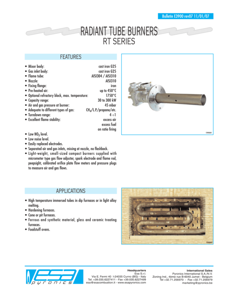
Bulletin E3900 rev07 11/01/07 RADIANT TUBE BURNERS RT SERIES FEATURES • • • • • • • • • • • • • • • • • Mixer body: cast iron G25 Gas inlet body: cast iron G25 Flame tube: AISI304 / AISI310 Nozzle: AISI310 Fixing flange: iron Pre-heated air: up to 450°C Optional refractory block, max. temperature: 1750°C Capacity range: 30 to 300 kW Air and gas pressure at burner: 45 mbar Adequate to different types of gas: CH4/L.P./propane/etc. Turndown range: 4 ÷1 Excellent flame stability: excess air excess fuel on ratio firing Low NOX level. Low noise level. Easily replaced electrodes. Separated air and gas inlets, mixing at nozzle, no flashback. Light-weight, small-sized compact burners supplied with micrometer type gas flow adjuster, spark electrode and flame rod, peepsight, calibrated orifice plate flow meters and pressure plugs to measure air and gas flows. F3900I01 APPLICATIONS • High temperature immersed tubes in dip furnaces or in light alloy melting. • Hardening furnaces. • Cone or pit furnaces. • Ferrous and synthetic material, glass and ceramic treating furnaces. • Foodstuff ovens. F3900I02 Headquarters Esa S.r.l. Via E. Fermi 40 I-24035 Curno (BG) - Italy Tel. +39.035.6227411 - Fax +39.035.6227499 esa@esacombustion.it - www.esapyronics.com International Sales Pyronics International S.A./N.V. Zoning Ind., 4ème rue B-6040 Jumet - Belgium Tel +32.71.256970 - Fax +32.71.256979 marketing@pyronics.be Bulletin E3900 rev07 11/01/07 DESCRIPTION The main feature of RT burners is the dual air mixing. The primary air mixes on the combustion head; the secondary air, guaranteed by holes on the flame tube, completes the mixing making the flame longer. This extends the life of the radiant tube and increase the heat transfer efficiency. Calibration of RT burners is simplified by plugs for gas and air flow controls. Air-gas ratio usually used in radiant tube burners are 12÷1, 13÷1. RT burners may operate with cold air and preheated air up 450° C (by using heat exchangers) allowing up to a 25-30% of energy saving. INSTALLATION RT burners may be mounted to operate in any position; installation is simplified by adjustable mounting flanges. Flexible connectors are recommended for air and gas connections to the burner to allow slight movement or misalignment of piping and are required when preheated air is involved. Air and gas connections are Pyronics standard threaded, or welding flanges. They may be rotated by 90°. IGNITION AND FLAME DETECTION Burner ignition is achieved by EN or WAND direct spark ignition electrode; a pilot burners may be supplied on request (only for the version listed on the table below). Flame detection is done by EN or Catalog No. WAND electrode and, on request, a UV-2 ultraviolet scanner may be used. Flame detection systems are required on all burners operating at furnace temperatures below 750° C. Pilot burner ignition Ignition Detection Ignition Electrode ignition Detection (*) RT - 1 - - Wand Wand RT - 2 - - Wand Wand RT - 3 P42PBST-W/X Wand 3EN / IS-4 3EN / IS-4 RT - 4 P42PBST-W/X Wand 3EN / IS-4 3EN / IS-4 RT - 5 - - 3EN / IS-4 3EN / IS-4 * UV 2 Optional CAPACITY TABLE Catalog No. Air/Gas pressure mbar Capacity kW @ 30 °C Capacity kW @ 400 °C Radiant tube diameter - mm RT - 1 45 30 20 70 ÷ 114 RT - 2 45 70 46 90 ÷ 150 RT - 3 45 150 100 130 ÷ 165 RT - 4 45 200 140 150 ÷ 210 RT - 5 45 300 195 168 ÷ 250 Capacity referred to Air/Gas ratio 12÷1 2/11 Bulletin E3900 rev07 11/01/07 MAXIMUM RADIANT TUBE DISSIPATION Operating temperature of furnace Maximum dissipation in kW/m2 AISI310 Maximum dissipation in kW/m2 SIC 1150 °C / 27,5 1100 °C / 55 1050 °C 18,0 78 1000 °C 22,6 100 950 °C 27,1 120 900 °C 30,7 137,5 850 °C 34,8 152,5 800 °C 38,4 165 750 °C 41,5 175 700 °C 45,1 187,5 HEAT EFFICIENCY Operating temperature of furnace in °C Straight and “U” non-recuperative tubes Straight and “U” recuperative tubes Recuperative tubes inlet-outlet on one side Maximum dissipation rate 22.6 kW/m2 dissipation rate Maximum dissipation rate 22.6 kW/m2 dissipation rate Maximum dissipation rate 22.6 kW/m2 dissipation rate 1050 42% – 56% – 64% – 1000 43% – 56% – 65% – 950 44% 45% 57% 58%* 67% 68%* 900 45% 47% 58% 60% 68% 70% 850 47% 49% 59% 61% 68% 70% 800 48% 51% 60% 63% 69% 72% 750 49% 52% 61% 64% 71% 74% 700 50% 54% 62% 65% 74% 74% * Experimental data - Other data are calculated. 3/11 Bulletin E3900 rev07 11/01/07 RT- 5 RT-4 RT-3 RT-2 RT-1 NATURAL GAS CAPACITY TABLE Pressure drop at orifice flow meter (mbar) 10 1 0,1 0,1 1 10 100 G3900I01 Natural gas flow @ 20°C P.S. = 0.6 (Nm3/h) N.B. Air/gas ratio in radiant tube burners are usually 12÷1, 13÷1. RT-5 RT-4 RT-3 RT-2 RT-1 AIR CAPACITY TABLE Pressure burner inlet (mbar) 100 10 1 0,1 1 10 100 1.000 G3900I02 Air flow @ 30°C P.S. = 1 (Nm3/h) N.B. Air/gas ratio in radiant tube burners are usually 12÷1, 13÷1. 4/11 Bulletin E3900 rev07 11/01/07 FLOW CHART WITHOUT RECUPERATOR D3900I01 Pos. Model identification Pos. Model identification 1 Gas ball valve 9 Gas adjuster 2 Zerogovernor 10 Manual air valve 3 Impulse line 11 Air orifice flow meter 4 Motorized air valve 12 Radiant tube burner 5 Electric control 13 Ignition transformer 6 Gas ball valve 14 Flame control 7 Safety solenoid valve 15 Radiant tube 8 Gas orifice flow meter 16 Premix air regulating group (only for LPG versions) 5/11 Bulletin E3900 rev07 11/01/07 FLOW CHART WITH RECUPERATOR D3900I02 Pos. Model identification Model identification Pos. 1 Gas ball valve 11 Gas adjuster 2 Zerogovernor 12 Gas orifice flow meter 3 Impulse line 13 Manual air valve 4 Air orifice flow meter 14 Air orifice flow meter 5 Electric control 15 Radiant tube burner 6 Motorized air valve 16 Flame control 7 Flow adjuster 17 Ignition transformer 8 Heat exchanger and flexible joint 18 Radiant tube 9 Gas ball valve 19 Premix air regulating group (only for LPG versions) 10 Safety solenoid valve 6/11 Bulletin E3900 rev07 11/01/07 DIMENSIONS (RT-1 / RT-2) D3900E03 Model øA øB C mm D mm E mm F mm G mm H mm I mm L mm M mm RT-1-CH4 Rp 1.1/2” Rp 1/2” 201 87 107 83 88 ø 48 ø 13 ø 120 ø 150 RT-1-GPL Rp 1.1/2” Rp 1/2” 201 87 107 83 88 ø 48 ø 13 ø 120 ø 150 RT-2-CH4 Rp 1.1/2” Rp 3/4” 226 101 107 110 88 ø 70 ø 13 ø 140 ø 170 RT-2-GPL Rp 1.1/2” Rp 1/2” 226 101 122 110 88 ø 70 ø 13 ø 140 ø 170 7/11 Bulletin E3900 rev07 11/01/07 DIMENSIONS (RT-3 / RT-4) D3900E04 Model øA øB C mm D mm E mm F mm G mm H mm I mm L mm M mm RT-3-CH4 Rp 2.1/2” Rp 1” 240 122 107 100 110 ø 101 ø 14 ø 200 ø 240 RT-3-GPL Rp 2.1/2” Rp 3/4” 240 122 122 100 110 ø 101 ø 14 ø 200 ø 240 RT-4-CH4 Rp 2.1/2” Rp 1.1/2” 256 122 117 108 110 ø 101 ø 14 ø 200 ø 240 RT-4-GPL Rp 2.1/2” Rp 1” 256 122 132 108 110 ø 101 ø 14 ø 200 ø 240 8/11 Bulletin E3900 rev07 11/01/07 DIMENSIONS (RT-3-P / RT-4-P) D3900E05 Model øA øB C mm D mm E mm F mm G mm H mm I mm L mm M mm N mm RT-3-CH4-P Rp 2.1/2” Rp 1” 240 122 107 100 110 ø 101 ø 14 ø 200 ø 240 370 RT-3-GPL-P Rp 2.1/2” Rp 3/4” 240 122 122 100 110 ø 101 ø 14 ø 200 ø 240 370 RT-4-CH4-P Rp 2.1/2” Rp 1.1/2” 256 122 117 108 110 ø 101 ø 14 ø 200 ø 240 370 RT-4-GPL-P Rp 2.1/2” Rp 1” 256 122 132 108 110 ø 101 ø 14 ø 200 ø 240 370 9/11 Bulletin E3900 rev07 11/01/07 DIMENSIONS (RT-5) D3900E06 10/11 Bulletin E3900 rev07 rev05 11/01/07 31/01/00 ORDERING CODE - BURNERS RT - - - - MODEL RT-1 1 RT-2 2 RT-3 3 RT-4 4 RT-5 5 Without Gas Adjuster FLANGING TYPE According to ESA drawings E* According to customer dwg. C FLANGED PIPE LENGHT “X” Please specify lenght (mm) ... (see dimension drawings) GAS AJUSTER With Gas Adjuster - GA* IGNITION AND DETECTION F Ignition/detection electrodes E* FUEL: Natural Gas CH4 LPG GPL Gasogene ( ) 1 Monoelectrode M Pilot burner ( ) P 2 GP * Standard configuration Note: 1 Special manufacture made according to gas features 2 Available only for version 3 and 4 (see “Ignition and flame detection”) NOTE: Based on the company’s policy aimed at a continuous improvement on product quality, ESA-PYRONICS reserves the right to bring changes to the technical characteristics of this device without previous notice. Our catalog updated to the latest version is available on our web site www.esapyronics.com and it is possible to download modified documents WARNING: When operating, this combustion system can be dangerous and cause harm to persons or damage to equipment. Every burner must be provided with a protection device that monitors the combustion. The installation, adjustment and maintenance operations should only be performed by trained and qualified personnel. 11/11


