Din Rail 8 Input / 8 Output Module IO88B01KNX
advertisement
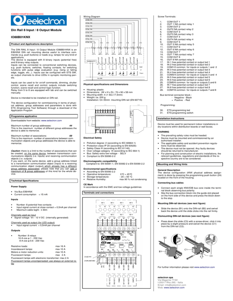
IO88B01KNXFI01040002.DOC Wiring Diagram Screw Terminals: Din Rail 8 Input / 8 Output Module IO88B01KNX Product and Applications description The DIN RAIL 8 Input / 8 Output Module IO88B01KNX is an EIB/KNX DIN rail mounting device useful to interface commands (e.g. push buttons) or loads (e.g. lamps) for any kind of applications. The device is equipped with 8 binary inputs (potential free) and 8 binary relay outputs. Inputs can be connected to conventional switching devices, e.g. push buttons, switches, floating contacts, for switching functions with pulse edge evaluation (e.g. rising or falling edge, toggle, etc...). Inputs can be configured with ETS SW, as output channels to drive LEDs in synoptic monitoring panels. Inputs can be used to for on/off commands, dimming, shutter control, scene recall and control; outputs include switching function, scene recall and control logic function. Relay from 5 to 8 are equipped with tab and can be switched manually Device is intended to be installed on DIN rail. Physical specifications and Dimensions • • • • Housing: plastic Dimensions: (W x H x D):: 70 x 90 x 58 mm Mounting width: 4 (1 SU=17,5mm) Weight: ca. 200 g. Installation: On 35mm mounting DIN rail (EN 60715) The device configuration for commissioning in terms of physical address, group addresses and parameters is done with ETS (Engineering Tool Software) through a download of the Application Program 1. 2. 3. 4. 5. 6. 7. 8. 9. 10. 11. 12. 13. 14. 15. 16. 17. 18. 19. 20. 21. 22. 23. 24. 25. 26. 27. 28. COM OUT 1 OUT 1 NA contact relay 1 COM OUT 2 OUT2 NA contact relay 2 COM OUT 3 OUT3 NA contact relay 3 COM OUT 4 OUT4 NA contact relay 4 COM OUT 5 OUT 5 NA contact relay 5 COM OUT 6 OUT 6 NA contact relay 6 COM OUT 7 OUT 7 NA contact relay 7 COM OUT 8 OUT 8 NA contact relay 8 IN 1 free potential contact or output led 1 IN 2 free potential contact or output led 2 COM1/2 common for inputs or outputs 1 and 2 IN 3 free potential contact or output led 3 IN 4 free potential contact or output led 4 COM3/4 common for inputs or outputs 3 and 4 IN 5 free potential contact or output led 5 IN 6 free potential contact or output led 6 COM5/6 common for inputs or outputs 5 and 6 IN 7 free potential contact or output led 7 IN 8 free potential contact or output led 8 COM7/8 common for inputs or outputs 7 and 8 Bus terminal connector block : - Negative - Black + Positive - Red Programming: 30. 31. ETS programming led ETS programming switch Programma applicativo Installation Instructions Downloadable from website: www.eelectron.com Device must be used for permanent indoor installations in dry locations within distribution boards or wall boxes. Maximum number of group addresses: 44 This is the maximum number of different group addresses the device is able to memorize. Maximum number of associations: 69 This is the maximum number of associations between communication objects and group addresses the device is able to memorize. Caution: there is a limit to the number of associations that can be created, on the same device, between transmission communications objects (i.e. inputs) and receiving communication objects (i.e. outputs) If you want, on the same device, add a group address linked to a transmission communication object (input) to a receiving communication object (output) which already has a different group address associated, please note that you can add a maximum of 5 group addresses of this kind for the whole device. WARNING Electrical Safety • • • • • • Pollution degree: 2 (according to IEC 60664-1) Protection class IP 20 (according to EN 60529): Safety Class III (according to IEC 61140) Over voltage category III (according to IEC 664-1) Bus: Safety extra low voltage - SELV Compliant to EN 50090-2-2 Electromagnetic compatibility Compliant to: EN 50081-1, EN 50082-2 e EN 50090-2.2 Technical Specifications Environmental specifications • According to EN 50090-2.2 • Operative temperature: • Storage temperature: • Relative Humidity: Power Supply CE Mark In accordance with the EMC and low voltage guidelines • Via Bus EIB/KNX • Current consumption Terminals and connections < 15 mA Inputs • • • 0°C + 45°C - 20 + 55 °C max 90 % not condensing • The prevailing safety rules must be heeded. • Device must be mounted and commissioned by an authorised installer. • The applicable safety and accident prevention regulations must be observed. • The device must not be opened. Any faulty devices should be returned to manufacturer. • For planning and construction of electric installations, the relevant guidelines, regulations and standards of the respective country are to be considered. Mounting and Wiring hints General Description The device configuration (KNX physical address assignment) is done by pressing the programming push button (24) located on the front of the housing. Connecting bus cables • Connect each single KNX/EIB bus core inside the terminal block observing bus polarity. • Slip the bus connection block into the guide slot placed on the front side of this device and press the block down to the stop. Mounting DIN-rail devices (see next figure) Number: 8 potential free contacts Input signal current at close contact = 0,5mA per channel Maximum cable leght: ≤ 30m • Slide the device (B1) onto the DIN-rail (B2) and swivel back the device until the slide clicks into the rail firmly. Channels used as input • Signal voltage Vn - 12 V DC (internally generated) Dismounting DIN-rail devices (see next figure) Channels used as output (for LED output) • Input signal current = 0,5mA per channel • Press down the slide (C3) with a screw-driver, click it into place by a slight pressure and swivel the device (C1) from the DIN-rail (C2). Outputs • Number: 8 relays 16 A cos φ 1 - 230 Vac 8 A cos φ 0.6 - 230 Vac Resistive loads: max 16 A Incandescent lamps: max 10 A Motors e motor reduction units: max 10 A Fluorescent lamps: max 2 A Fluorescent lamps with electronic transformer: max 2 A Fluorescent lamps uncompensated: use always an external relay Mmmm For further information please visit www.eelectron.com eelectron spa Via Magenta 77/22 I-20017 Rho (MI) - Italia Email: info@eelectron.com Web: www.eelectron.com
