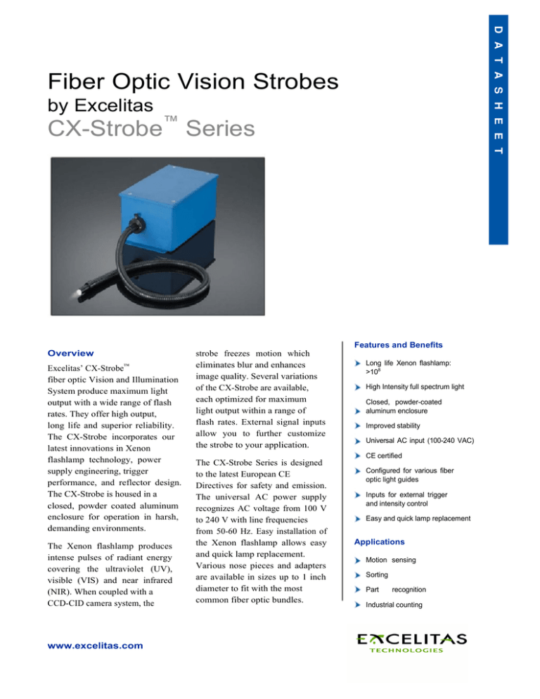
Fiber Optic Vision Strobes
by Excelitas
CX-Strobe™ Series
Features and Benefits
Overview
Excelitas’ CX-Strobe™
fiber optic Vision and Illumination
System produce maximum light
output with a wide range of flash
rates. They offer high output,
long life and superior reliability.
The CX-Strobe incorporates our
latest innovations in Xenon
flashlamp technology, power
supply engineering, trigger
performance, and reflector design.
The CX-Strobe is housed in a
closed, powder coated aluminum
enclosure for operation in harsh,
demanding environments.
The Xenon flashlamp produces
intense pulses of radiant energy
covering the ultraviolet (UV),
visible (VIS) and near infrared
(NIR). When coupled with a
CCD-CID camera system, the
www.excelitas.com
strobe freezes motion which
eliminates blur and enhances
image quality. Several variations
of the CX-Strobe are available,
each optimized for maximum
light output within a range of
flash rates. External signal inputs
allow you to further customize
the strobe to your application.
Long life Xenon flashlamp:
>108
High Intensity full spectrum light
Closed, powder-coated
aluminum enclosure
Improved stability
Universal AC input (100-240 VAC)
CE certified
The CX-Strobe Series is designed
to the latest European CE
Directives for safety and emission.
The universal AC power supply
recognizes AC voltage from 100 V
to 240 V with line frequencies
from 50-60 Hz. Easy installation of
the Xenon flashlamp allows easy
and quick lamp replacement.
Various nose pieces and adapters
are available in sizes up to 1 inch
diameter to fit with the most
common fiber optic bundles.
Configured for various fiber
optic light guides
Inputs for external trigger
and intensity control
Easy and quick lamp replacement
Applications
Motion sensing
Sorting
Part
recognition
Industrial counting
CX-Strobe™ TECHNICAL SPECIFICATIONS
Optical Specifications
CX-Strobe
CX-1500
Maximum flash rate1
Input energy per flash2
Light output flash duration3
Photometric light output4
Photometric light output5
Photometric light output6
Radiometric light output4
Radiometric light output5
Radiometric light output6
Spectral bandwidth
Flashlamp life7
Discharge Capacitance
CX-1200
CX-400
15 Hz (0 - 35 Hz)
1.2 J - 2.7 J
8 - 10 µsec
34 lumen-sec
22 lumen-sec
9.3 lumen-sec
265 mJ
165 mJ
73 mJ
250 - 1100+ nm
20 Hz (0 - 45 Hz)
1.0 - 2.2 J
8 - 10 µsec
31 lumen-sec
19 lumen-sec
8.5 lumen-sec
225 mJ
145 mJ
65 mJ
250 - 1100+ nm
60 Hz (0 - 135 Hz)
0.3 - 0.7 J
8 - 10 µsec
12 lumen-sec
8.5 lumen-sec
4.2 lumen-sec
90 mJ
60 mJ
30 mJ
250 - 1100+ nm
> 108
> 108
> 2 x 10⁸
15 µF
12 µF
4 µF
High intensity may cause damage to plastic fiber optic light guides. Contact the fiber manufacturer for temperature limits.
Electrical Specifications
Environmental Specifications
Input voltage
Maximum output power
Input current (rms)
Flashlamp voltage8
Remote intensity control9
External trigger input10
Operating temperature
Storage temperature
100 - 240 VAC (±10%), 50 - 60 Hz
43 W
1.5 A @ 115 VAC
400 - 600 VDC
4 - 6 VDC (Vref: Vlamp = 1:100)
+5 V TTL pulse, 20 mA, 10 - 100 µsec
All Values are nominal; specifications subject to change without notice.
1
2
3
Maximum flash rate at 600 VDC; the numbers in parenthesis represent
the range of flash rates at adjusted lamp voltage (400 - 600 VDC).
Flash rate = 43/E where energy per flash, E = 1/2 Capacitance x Voltage2
(E = 1/2 CV2).
Energy at 400 - 600 VDC.
Approximate values measured at 1/3 peak of light pulse.
0 to +40º C (32 to +104º F)
-40 to +90º C (-40 to +194º F)
4
Approximate light output at 600 VDC into 0.9 inches (23mm)
diameter fiber optic light guide. Numerical aperture 0.5.
Approximate light output at 600 VDC into 0.5 inches (13mm)
fiber optic light guide.
6
Approximate light output at 600 VDC into 0.27 inches (7mm)
fiber optic light guide.
7
Maintaining > 70% light output.
8 Increasing lamp voltage will reduce lamp life.
9 Also available Vref:Vlamp = 1:60.
10
Delay between flash command and light output is 8 µsec typical.
Optional fiber optic nose pieces: Fostec 0.72 inches ID (MVS 23),
Volpi 0.59 inches ID (MVS 24), or Dolan Jenner 1.0 inch ID (MVS 25).
5
MECHANICAL SPECIFICATIONS
*All values are nominal; specifications subject to change without notice.
Salem, MA USA
Excelitas Technologies
35 Congress Street
Salem, MA 01970
Telephone: 978-745-3200 Toll
free: (800) 950-3441 (USA) Fax:
978-745-0894
generalinquiries@excelitas.com
www.excelitas.com
European Headquarters
Excelitas Technologies
Wenzel-Jaksch-Str. 31
65199 Wiesbaden, Germany
Telephone: (+49) 611-492-247
Fax: (+49) 611-492-170
Asia Headquarters
Excelitas Technologies
47 Ayer Rajah Crescent #06-12
Singapore 139947
Telephone: (+65) 6775-2022
Fax: (+65) 6775-1008
Vision Light Tech
Protonenlaan 22
NL-5405 NE UDEN
The Netherlands
Telephone: +31 (0)413 260067
Fax: +31 (0)413 260938
For a complete listing of our global offices, visit www.excelitas.com
©2011 Excelitas Technologies Corp. All rights reserved. The Excelitas logo and design are registered trademarks of Excelitas Technologies Corp. CX-Strobe is a trademark of Excelitas
Technologies Corp. or its subsidiaries in the United States and other countries. All other trademarks not owned by Excelitas Technologies or its subsidiaries that are depicted herein are
the property of their respective owners. Excelitas reserves the right to change this document at any time without notice and disclaims liability for editorial, pictorial or typographical
errors.
600166_01 DTS1106P


