SELECTABLE OUTPUT STROBES AND HORN/STROBES
DESCRIPTION
Fike’s Selectable Output Horns, Strobes, and Horn/Strobes, manufactured by
System Sensor, offer enhanced features that include the widest range of candela
options available and the capability to recognize and self-adjust for either 12
or 24 volt operation. With an overall feature set that combines performance,
installation ease, flexibility, and a consistent, aesthetically pleasing appearance,
the Fike Selectable Output devices provide both the innovation and efficiency
synonymous with the Fike name.
Offering key performance features long associated with the Fike name, the
selectable candela strobes and horn/strobes offer average current draws that are
not only lower than conventional fixed-candela Fike products, but also lower
than similar selectable candela products. By consuming less current, the ability to
connect even more devices per loop is possible, resulting in a lower installed cost.
Fike’s selectable output horns, strobes, and horn/strobes offer the same
installation-friendly features, such as the option of 2- and 4-wire operation, the
ability to use standard size back boxes with no encroachment into the box, and
universal mounting incorporating the labor-saving QuickClick™ feature. Such
labor-saving features make wire connections simple and fast, further reducing
installed cost.
The selectable output strobes and horn/strobes offer the broadest range of
candela options, operating on either 12V or 24V, with no setting required;
the device recognizes and self-adjusts to the correct current automatically.
Temporal 3 or continuous tone options continue to be available, in either an
electromechanical or 3kHz pattern.
In addition, all strobe and horn/strobe models incorporate a new voltage booster
design that has a more consistent flash bulb voltage over the range of candela
selections. The benefit to the customer is a high quality strobe device.
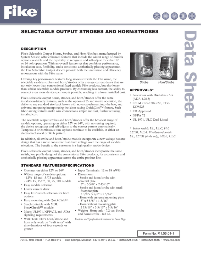
Strobe
Horn/Strobe
APPROVALS*
• Americans with Disabilities Act
(ADA 4.28.3)
• CSFM 7125-1209:222 ; 71351209:223
• FM Approved
• NFPA 72
• UL 1971, ULC Dual Listed
* Indoor models: UL, ULC, FM,
CSFM, MEA. Weatherproof models:
UL, CSFM (strobe only), MEA, ULC.
Fike’s selectable output horns, strobes, and horn/strobes incorporate the same
stylish, low profile design of the conventional Fike products, for a consistent and
aesthetically pleasing appearance across the entire product line.
STANDARD FEATURES/SPECIFICATIONS
• Operates on either 12V or 24V
• Input Terminals: 12 to 18 AWG
• Dimensions:
• Widest range of candela options:
- 12V: 15 and 15/75 candela
- Strobe and horn/strobe with
- 24V: 15, 15/75, 30, 75, 110 candela
universal plate
5” x 5-5/8” x 2-15/16”
• Easy candela selection
Strobe
and horn/strobe with small
• Lower current draw
footprint plate
• Easy DIP switch selection for horn
3 3/8”x 5 5/8” x 2 5/16”
options
- Horn with universal mounting plate
• Easy mounting with QuickClickTM
5” x 5 5/8” x 1-5/16”
- Horn without mounting plate
• Synchronizable with MDL
2 15/16” x 5 5/16” x 1-5/16”
Sync•CircuitTM module
• Meets UL1971, NFPA72, and ADA • Weight: Horn only - 7.2 oz.; Strobe
and horn/strobe - 8.8 oz.
signaling requirements
• Walk Test: Fike’s horn/strobe and
horn only work on “walk tests” with
time durations of four seconds or
greater
Features and Specifications Continued on Next Page.
Form No. P.1.56.01-1
704 S. 10th Street · P.O. Box 610 · Blue Springs, Missouri 64013-0610 U.S.A. · (816) 229-3405 · (816) 229-4615 · www.fike.com
STANDARD FEATURES/SPECIFICATIONS (Cont.)
• Mounting: 4” x 4” x 1 1/2” or 2” x 4” x 1 7/8”
• Operating voltage range:* 12V: 8–17.5V; 24V: 16–33V
standard boxes
• Operating voltage range* (with Sync•Circuit module,
• Indoor Operating Temperature: 32o to 120oF (0o to
20-130-26): 12V: 9–17.5V; 24V: 17–33V
49oC)
• U.S. Patent Numbers: 5,593,569; 5,914,665; 6,049,446
• Maximum humidity: 95% as tested per UL464
• Operating Temperatures:
* Do not exceed; 1) 16–33 or 8–17.5 voltage range limit; 2)
- Weatherproof (horn and horn/strobes)- 32o to 150oF
maximum number of 70 strobe lights when connecting the 20-130(0o to 66oC)
26 Sync module with a maximum line impedance of 4 ohms per
- Outdoor strobe only - –40o to 158oF (–40o to 70oC)
loop and; 3) maximum line impedance as required by the fire alarm
- ULC Canadian Models - –40o to 66oC
control manufacturer.
• Voltages: 12 or 24VDC and FWR unfiltered
Current Draw
FWR Operating
DC Operating
FWR Operating
DC Operating
Horn
Candela Current - Strobe (ma Current - Strobe (mA Current - Horn (mA Current - Horn (mA
Audibility
RMS)
RMS)
RMS)
RMS)
Setting
(dBA)
12V
24V
12V
24V
12V
24V
12V
24V
Models
Selectable
Strobes
Selectable
Horn/Strobes
Horns
15
112
64
127
15/75
30
75
59
-
-
-
-
-
135
74
127
-
93
-
69
-
-
-
-
-
90
-
-
-
-
-
158
-
160
-
-
-
-
-
-
110
-
208
-
209
-
-
-
-
-
15
112
64
127
59
45.7
57.5
44.4
57
75
15/75
135
74
127
69
45.7
57.5
44.4
57
75
30
-
93
-
90
-
57.5
-
57
75
75
-
158
-
160
-
57.5
-
57
75
110
-
208
-
209
-
57.5
-
57
75
-
-
-
-
-
45.7
57.5
44.4
57
75
MOUNTING AND OPERATION
Permissible Candela Settings
12 and 24 operating voltage permissible for all candela
settings except, 12 V not permissible for 30,75 and 110
Candela.
Candela Selections
For strobe candela selection, adjust slide switch located on
the rear of the product while watching the viewing window
on the side of the reflector.
Viewing Window
Typical Weatherproof Mounting with Universal Plate
Dip Switch Operation
OFF
Low
Temporal
Electromech.
ON
Factory
Default
WBB
DIP Switch
Plate
#8-36 x 1/2″ Flat Head
Screw (4 total)
High
Non-Temporal
3000Hz
Base (rear)
Selectable Horn Tones
Selectable horn tones for temporal and non-temporal, low
and high volume is electromechanical, 3000 Hz interrupted.
Gasket
Conduit
Entrance
Slot
Paper Liner
For Plate
Gasket
Locking Rib
AVAILABLE MODELS
Fike P/N
Manf. P/N
Description
20-130-140
P1224MC
Selectable Output Horn/Strobe, Red
20-130-141
P1224MCW
Selectable Output Horn/Strobe, White
20-130-149
P1224MCP
Selectable Output Horn/Strobe, 12/24 volt, Red, Plain housing
20-130-150
P1224MCPW
Selectable Output Horn/Strobe, 12/24 volt, White, Plain housing
20-130-148
P1224MCK
Selectable Output Horn/Strobe, 12/24 volt, Red Weatherproof
20-130-151
P1224MCSP
Selectable Output Horn/Strobe, 12/24 volt, Red “FUEGO” housing
20-130-142
S1224MC
Selectable Output Strobe, Red
20-130-143
S1224MCW
Selectable Output Strobe, White
20-130-152
S1224MCP
Selectable Output Strobe, 12/24 volt, Red, Plain housing
20-130-153
S1224MCPW
Selectable Output Strobe, 12/24 volt, White, Plain housing
20-130-147
S1224MCK
Wall-Mount Weatherproof Strobe Multi-CD, 120 VAC
20-130-154
S1224MCSP
Selectable Output Strobe, 12/24 volt, Red, “FUEGO” housing
20-130-116
H12/24
Wall Mount Horn, Red
20-130-118
H12/24W
Wall Mount Horn, White
20-130-117
H12/24K
Weatherproof Wall Mount Horn, Red
20-130-26
MDL
Sync Circuit Module, Red
20-130-27
MDLW
Sync Circuit Module, White
20-1069
MDLA
Sync Circuit Module, Red, Canadian Model
20-1070
MDLWA
Sync Circuit Module, White, Canadian Model
20-130-28
S-MP
Mounting Plate for Single Gang, Red, Small Footprint
20-130-29
S-MPW
Mounting Plate for Single Gang, White, Small Footprint
Accessories
20-130-30
BBS
Wall Mount Back Box Skirt, Red, Surface Mount
20-130-31
BBSW
Wall Mount Back Box Skirt, White, Surface Mount
20-130-32
20-130-33
D-MP
Universal Mounting Plate, Red
D-MPW
Universal Mounting Plate, White
NOTE: All of these products are designed for wall mount only. All weatherproof models must use weatherproof back box model 20-130-34.
Installation of less than 75 candela strobes may be permissible under the equivalent facilitation clause of the ADAAG (Sec. 2.2). However, it is
the responsibility of the person or entity designing the fire alarm system to determine the acceptability of less than 75 candela strobes. All 15/75
candela strobes or horn/strobes are recommended for 20’ x 20’ rooms or less.
ARCHITECT AND ENGINEERING SPECIFICATIONS
General
The horns, strobes and horn/strobes shall be capable of mounting to a standard 4”x4”x 1 1/2” back box or a single gang
2”x 4”x1 7/8” back box using the universal mounting plate included with each Fike product. Also, Fike’s products, when
used in conjunction with the accessory Sync•Circuit Module, shall be powered from a non-coded power supply and shall
operate on 12 or 24 volts. 12 volt rated devices shall have an operating voltage range of 9–17.5 volts. 24-volt rated devices
shall have an operating voltage range or 17–33 volts. Fike’s products shall have an operating temperature of 32° to 120°F
and operate from a regulated DC or full wave rectified, unfiltered power supply.
Strobe
Strobe shall be a System Sensor Model _______ listed to UL 1971 and be approved for fire protective service. The
strobe shall be wired as a primary signaling notification appliance and comply with the Americans with Disabilities Act
requirements for visible signaling appliances, flashing at 1Hz over the strobe’s entire operating voltage range. The strobe
light shall consist of a xenon flash tube and associated lens/reflector system.
Horn/Strobe Combination
Horn/Strobe shall be a System Sensor Model _______ listed to UL 1971 and UL 464 and shall be approved for fire
protective service. Horn/strobe shall be wired as a primary signaling notification appliance and comply with the Americans
with Disabilities Act requirements for visible signaling appliances, flashing at 1Hz over the strobe’s entire operating voltage
range. The strobe light shall consist of a xenon flash tube and associated lens/reflector system. The horn shall have two
tone options, two audibility options (at 24 volts) and the option to switch between a temporal 3 pattern and a non-temporal
continuous pattern. Strobes shall be powered independently of the sounder with the removal of factory installed jumper
wires. The horn on horn/strobe models shall operate on a coded or non-coded power supply (the strobe must be powered
continuously).
Synchronization Module
Module shall be a System Sensor Sync•Circuit _______ listed to UL 464 and shall be approved for fire protective service.
The module shall synchronize the strobes at 1Hz and horns at temporal 3. Also, the module shall silence the horns on
horn/strobe models, while operating the strobes, over a single pair of wires. The module shall be capable of mounting to a
4 11/16”x 4 11/16”x 2 1/8” back box and shall control two Style Y (class B) or one Style Z (class A) circuit. Module shall
be capable of multiple zone synchronization by daisy chaining multiple modules together and re-synchronizing each other
along the chain. The module shall not operate on a coded power supply.
R
Copyright © Fike Corporation All Rights Reserved.
Form No. P.1.56.01-1 August, 2005 Specifications are subject to change without notice.


