Quick reference guide "Installation and connection"
ATICS-2-…-DIO / ATICS-4-…-DIO
Automatic transfer switching devices for safety power supplies
This reference guide does not replace the operating manual. You will find the operating manual on the CD accompanying the device or in the
download area of our homepage. Make sure that the personnel has read this manual and understood all instructions relating to safety.
1. Safety instructions
Danger: Risk of fatal injury from electric shock
Parts of the system are live. During installation and connection:
► Do not touch parts of the system.
► Make sure that the power supply has been disconnected and the
system is dead.
► Switch the ATICS® to manual mode and to switch position "0".
► Lock the changeover device with a padlock to prevent it starting
accidently.
►
Danger: Risk of fatal injury from electric shock
Connecting wires can come loose and fall out if the ferrules being used
are too short, the wire ends are tinned or the connection screws have
not been tightened enough.
► Consider a stripping length of 20 mm (15 mm for ATICS-4-160ADIO) and do not use ferrules when connecting lines 1, 2 and 3.
► Use a torque wrench to tighten the terminal screws. Check all
the screws on a regular basis to make sure they are seated
tightly.
Warning: Risk of destruction if mains voltage incorrect
The permissible mains voltage is indicated on the nameplate.
2. Scope of delivery
3. Other system components required
• Alarm indicator and test combination MK… or/and alarm indicator and operator panel TM…
• Bypass switch (recommended for ATICS-2-DIO)
• For screw mounting only: mounting screws M5
ATICS® transfer switching device
• including connectors, bridge and terminal covers
• Measuring current transformer STW3 resp. STW4
Documentation
• CD with ATICS® operating manual and operating manuals of
other system components
• Quick reference guides and checklist
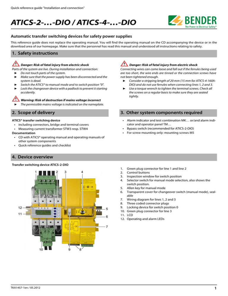
4. Device overview
Transfer switching device ATICS-2-DIO
1
2
3
1.
2.
3.
4.
4
12
5
11
6
Green plug connector for line 1 and line 2
Control buttons
Inspection window for switch position
Selector switch for manual mode selection, also shows the
switch position.
5. Allen key for manual mode
6. Transparent cover for changeover switch (manual mode), sealable
7. Wiring diagram for lines 1, 2 and 3
8. Three coded connector plugs
9. Locking device for switch position 0
10. Green plug connector for line 3
11. LCD
12. Operating and alarm LEDs
7
10
TKA1457-1en / 05.2012
9
8
1
ATICS-2-…-DIO / ATICS-4-…-DIO
Transfer switching device ATICS-4-DIO
1
2
3
4
1.
2.
3.
4.
5.
5
6.
7.
8.
9.
10.
11.
12.
13.
14.
6
14
7
8
13 12 11
10
Green plug connector for line 1
Green plug connector for line 2
Control buttons
Inspection window for switch position
Selector switch for manual mode selection, also shows the
switch position.
Allen key for manual mode
Transparent cover for changeover switch (manual mode), sealable
Wiring diagram for lines 1, 2 and 3
Three coded connector plugs
Locking device for switch position 0
Green plug connector for line 3
LCD
Operating and alarm LEDs
Connector plug for measuring current transformers
9
5. Dimensions
ATICS-2-DIO
52
ATICS-4-DIO
340
234
176 ***
52
104
176
***
14,7
115,3
14,7
115,3
M5
*
45
*
245
132
****
132
23
263
45
132
245
263
132
***
***
M5
15
18
18
220
324
326 **
47
46
52
73,5
46
53
73,5
47
222 **
* Additional space required for the auxiliary contact when using a bypass switch
** Adapt the cutout to the terminal cover
*** Dimensions for screw mounting on mounting plate
6. Tools required
►
2
We recommend to use the following tools for connecting the
power section and the control cables:
• Screwdriver PZ2 or 6.5 x 1.2 mm
• Screwdriver 2.5 x 0.4 mm
• Allen key 4 mm
TKA1457-1en / 05.2012
ATICS-2-…-DIO / ATICS-4-…-DIO
7. Removing the terminal covers
1.
2.
Push back the locking hook (B) in the middle of the top and
bottom terminal cover (A) by using a screwdriver.
Remove the terminal cover.
1.
Place the ATICS® on the top edge of the rail.
2.
ATICS-2-DIO: Use a screwdriver to pull down the lower yellow
slide lock (C) and snap the ATICS® into place with slight pressure.
ATICS-4-DIO: Remove bottom green plug connector. Use
screwdrivers to pull down the two lower yellow slide lock (C)
and snap the ATICS® into place with slight pressure.
Check that the slide locks are properly snapped into position
by pulling slightly the lower part of the enclosure.
3.
Secure all terminals including the unused terminals with Allen
screws.
Tightening torque: 5 Nm.
Fasten the terminal covers.
A
B
B
A
8. Mounting the ATICS® on DIN rail
C
4.
5.
Tighten the mounting screws (D) (PZ1, 8.8 lb-in, 1 Nm). The
screws prevent the device from slipping sideways on the rail.
D
TKA1457-1en / 05.2012
3
ATICS-2-…-DIO / ATICS-4-…-DIO
9. Mounting the ATICS® on mounting plate
Warning: Screw heads or washers reduce voltage clearance
Provide for sufficient clearance to live conductors (voltage clearance) by using mounting screws with flat screw heads and flat washers. If mounted on
electrically conductive material: the mounting plate has to be earthed and the area under the terminals has to be covered with insulating material. It is
the responsibility of the mounting staff to select the appropriate mounting plate and mounting screws and to keep the prescribed torque setting.
1.
2.
3.
4.
C
5.
6.
7.
D
E
8.
Undo the Allen screws of the terminals (C).
Remove the green plug connectors (D) top and bottom
Remove the black bridge (E) bottom
Fasten the ATICS® to the mounting plate with M5 mounting
screws, torque setting 22 lb-in, 2.5 Nm (see dimension diagram).
Insert the black bridge (E), bottom
Plug in the green plug connectors (D) top and bottom
Use Allen screws to tighten all terminals (C) including the
unused terminals.
Tightening torque: 5 Nm.
Fasten the terminal covers.
10. Fastening, inserting and securing connections
A
B
Connect the terminals according to the wiring diagram to the plug
connectors (A, B) and the connector plugs (C, D).
• Connect the lines 1, 2 and 3 to the plug connectors (A,B) with a
Phillips screwdriver PZ2 or a slotted screwdriver 6.5 x 1.2 mm.
Consider a stripping length of 20 mm and do not use ferrules.
Tightening torque: 2.5…4.5 Nm. The connecting wires must
be laid so that they are short-circuit and earth-fault proof!
• Connect the three connector plugs (C) with a slotted screwdriver of 2.5 x 0.4 mm. Stripping length: 7 mm. Tightening
torque: 0.22…0.25 Nm.
1.
2.
3.
4
Insert bottom green plug connector (B) and secure with
mounting screws.
ATICS-2-DIO: After that, insert top green plug connector (A)
and secure with mounting screws.
ATICS-4-DIO: After that, insert the two top green plug connectors and secure with mounting screws.
Insert the three connector plugs (C).
ATICS-4-DIO only:
Insert the connector plug (D) of the measuring current transformers T1 … T4 (D).
Note: The plug must noticeably click into place!
TKA1457-1en / 05.2012
ATICS-2-…-DIO / ATICS-4-…-DIO
11. Wiring diagrams
Connection ATICS-2-DIO
Line 2
AC 230 V
50 Hz
Independent
supply lines
AC 230 V 50 Hz
*These terminals are solely intended
for the connection to the
energy storage device ATICS-ES!
dig.
input 1
white
Relay.
outputs 2…4
grey
dig.
inputs 2…4
Line 1
AC 230 V
50 Hz
L1
L2
distribution board
AC 230 V 50 Hz
black
Relay
output 1
Min. 2 groups of
MK2430 / MK800 resp. TM800
Terminal
Meaning
1L, 1N
Connection line 1 (input line)
2L, 2N
Connection line 2 (input line)
L, N
Connection line 3 (output line)
l, k
Connection measuring current transformer STW3 (T3) for monitoring the load current downstream
the transfer switching device (short-circuit monitoring)
GND, En/Ex
Connection external energy storage device ATICS-ES (12 V)
IN1/GND, IN1
Digital input, configurable, for example, for monitoring the switch position of the changeover
function
NC, NC
24, 34, 44, 21
IN2, IN3, IN4, IN2-4 GND
not used
3 alarm relays (1 N/O contact each), 21 = common connection for the three alarm relays
3 digital inputs
A, B
BMS bus connection
14, 12, 11
Alarm relay, programmable function
TKA1457-1en / 05.2012
5
ATICS-2-…-DIO / ATICS-4-…-DIO
Connection ATICS-4-DIO
Line 1
3/N AC 400 V
50 Hz
Line 2
3/N AC 400 V
50 Hz
Independent
supply lines
AC 230 V 50 Hz
*These terminals are solely intended
for the connection of subsequent expansions
Connection measuring
current transformers
grey
white
dig.
inputs 2…4
dig.
input 1
Relay.
outputs 2…4
Optional connection T6
L1 L2 L3 N
distribution board
3/N AC 400V
50 Hz
black
Relay
output 1
Min. 2 groups of
MK2430 / MK800 resp. TM800
Terminal
L1, L1-1, L2-1, L3-1, N1
Meaning
Connection line 1 (input line)
L2, L1-2, L2-2, L3-2, N2
Connection line 2 (input line)
L3, L1-3, L2-3, L3-3, N3
Connection line 3 (output line)
NC, NC
not used
GND, En/Ex
Connection for subsequent expansions (12V)
IN1/GND, IN1
Digital input, configurable, for example, for monitoring the switch position of the changeover
function
NC, NC
24, 34, 44, 21
IN2, IN3, IN4, IN2-4 GND
not used
3 alarm relays (1 N/O contact each), 21 = common connection for the three alarm relays
3 digital inputs
A, B
BMS bus connection
NC, NC, NC
not used
14, 12, 11
l1, l2, l3, l4,
k1, k2, k3, k4
Alarm relay, programmable function
Connection measuring current transformer T1 (T4) for monitoring the load current downstream the
transfer switching device (short-circuit monitoring).
Note: Insert the plug until it noticeably clicks into place!
All rights reserved.
Reprinting and duplicating
only with permission of the publisher.
Subject to change!
© Bender GmbH & Co. KG
Bender GmbH & Co. KG
Londorfer Str. 65 • 35305 Grünberg • Germany
P.O.Box 1161 • 35301 Grünberg • Germany
6
Tel.: +49 6401 807-0
Fax: +49 6401 807-259
E-mail: info@bender-de.com
Web: http://www.bender-de.com
TKA1457-1en / 05.2012


