PRELIMINARY
HT-0325-10
Silicon Carbide Bridge Rectifier
High Performance Hermetic Discrete
VDC
ID @ 185 °C
QC @ 25 °C
Ultra-Fast Schottky Diode
Features
650 V
4.5 A
25 nC
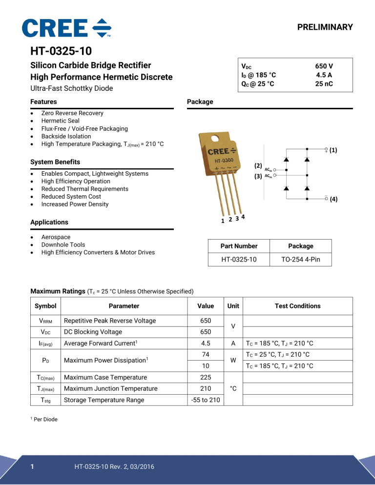
Package
Zero Reverse Recovery
Hermetic Seal
Flux-Free / Void-Free Packaging
Backside Isolation
High Temperature Packaging, TJ(max) = 210 °C
(1)
System Benefits
(2)
Enables Compact, Lightweight Systems
High Efficiency Operation
Reduced Thermal Requirements
Reduced System Cost
Increased Power Density
(3)
(4)
4
1 2 3
Applications
Aerospace
Downhole Tools
High Efficiency Converters & Motor Drives
Part Number
Package
HT-0325-10
TO-254 4-Pin
Maximum Ratings (Tc = 25 °C Unless Otherwise Specified)
Symbol
Repetitive Peak Reverse Voltage
650
VDC
DC Blocking Voltage
650
Average Forward Current1
4.5
74
PD
Maximum Power Dissipation1
TC(max)
Maximum Case Temperature
225
TJ(max)
Maximum Junction Temperature
210
Tstg
Storage Temperature Range
Per Diode
1
Value
VRRM
IF(avg)
1
Parameter
HT-0325-10 Rev. 2, 03/2016
10
-55 to 210
Unit
Test Conditions
V
A
W
°C
TC = 185 °C, TJ = 210 °C
TC = 25 °C, TJ = 210 °C
TC = 185 °C, TJ = 210 °C
PRELIMINARY
SiC Diode Electrical Characteristics (Tc = 25 °C Unless Otherwise Specified)
Symbol
VF
Parameter
Diode Forward Voltage
IR
Reverse Current
Qc
Total Capacitive Charge
Min.
Typ.
Max.
1.5
1.8
2.0
2.4
2.2
2.6
12
60
150
220
Unit
IF = 10 A, TJ = 25 °C
IF = 10 A, TJ = 175 °C
V
IF = 10 A, TJ = 210 ° C
μA
25
nC
Total Capacitance
VR = 6500 V, TJ = 25 °C
VR = 1200 V, TJ = 200 °C
VR = 650 V, IF = 10 A,
diF/dt = 500 A/μs, TJ =25 °C
VR = 0 V, TJ = 25 °C, f = 1 MHz
480
C
Test Conditions
50
pF
VR = 200 V, TJ = 25 °C, f = 1 MHz
VR = 400 V, TJ = 25 °C, f = 1 MHz
42
Thermal & Mechanical Characteristics
Symbol
RΘ(J-C)
Parameter
Diode Thermal Resistance, J to C
W
Weight
Ms
Mounting Torque
Value
Unit
2.5
°C/W
9
g
0.8
N-m
Package Dimensions [in(mm)]
Fig 1. Dimensions
2
HT-0325-10 Rev. 2, 03/2016
Test Conditions
6-32 Bolt
PRELIMINARY
Important Note
Some values were obtained from the CPW2-0650-S010B Rev. A device datasheet.
THE PRODUCT DESCRIBED IS AN ENGINEERING SAMPLE THAT IS NOT INTENDED FOR PRODUCTIVE USE,
IS CURRENTLY AVAILABLE FOR EVALUATION AND TESTING PURPOSES ONLY, AND IS PROVIDED “AS IS”
WITHOUT WARRANTY OF ANY KIND, INCLUDING BUT NOT LIMITED TO ANY WARRANTY OF NONINFRINGEMENT, MERCHANTABILITY, OR FITNESS FOR PARTICULAR PURPOSE. Suitability of this product for
any application may depend on product parameters not specified this document. The buyer is solely responsible for
determining such additional product details.
The data and information contained in this document is preliminary and is subject to change due to further product
evaluation and testing and/or product modifications. Accordingly, buyers are cautioned to evaluate actual products
against their needs and not to rely solely on the data and information presented in this document.
The product described has not been designed or tested for use in, and is not intended for use in, applications implanted
into the human body or in applications in which failure of the product could lead to death, personal injury or property
damage, including but not limited to equipment used in the operation of nuclear facilities, life-support machines, cardiac
defibrillators or similar emergency medical equipment, vehicle navigation, communication or control systems, or air
traffic control systems.
The product described is not eligible for Distributor Stock Rotation or Inventory Price Protection.
Copyright © 2014 - 2016 Cree Fayetteville, Inc. All rights reserved.
The information in this document is subject to change without notice.
Cree®, and Zero Recovery® are registered trademarks and the Cree logo is a
trademark
of Cree,
Inc. Rev. 2, 03/2016
3
HT-0325-10
For Purchasing: Email HighPerformanceSales@cree.com
Cree Fayetteville, Inc.
535 W Research Center Blvd
Fayetteville, AR 72701
USA Tel: +1.479.443.5759
www.apei.net


