OUTPUT CONFIGURATIONS
AND CONNECTIONS
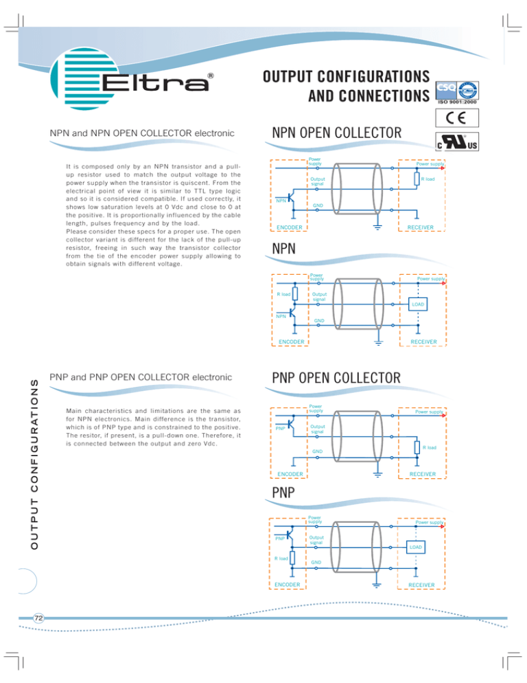
NPN and NPN OPEN COLLECTOR electronic
It is composed only by an NPN transistor and a pullup resistor used to match the output voltage to the
power supply when the transistor is quiscent. From the
electrical point of view it is similar to TTL type logic
and so it is considered compatible. If used correctly, it
shows low saturation levels at 0 Vdc and close to 0 at
the positive. It is proportionally influenced by the cable
length, pulses frequency and by the load.
Please consider these specs for a proper use. The open
collector variant is different for the lack of the pull-up
resistor, freeing in such way the transistor collector
from the tie of the encoder power supply allowing to
obtain signals with different voltage.
NPN OPEN COLLECTOR
Power
supply
Output
signal
Power supply
R load
NPN
GND
ENCODER
RECEIVER
NPN
Power
supply
R load
Power supply
Output
signal
LOAD
NPN
GND
O U T P U T C O N F I G U R AT I O N S
ENCODER
PNP and PNP OPEN COLLECTOR electronic
Main characteristics and limitations are the same as
for NPN electronics. Main difference is the transistor,
which is of PNP type and is constrained to the positive.
The resitor, if present, is a pull-down one. Therefore, it
is connected between the output and zero Vdc.
PNP OPEN COLLECTOR
Power
supply
PNP
Power supply
Output
signal
R load
GND
ENCODER
RECEIVER
PNP
Power
supply
PNP
Power supply
Output
signal
LOAD
R load
ENCODER
72
RECEIVER
GND
RECEIVER
PUSH-PULL
PUSH-PULL electronic
Power
supply
Output
signal
LOAD
GND
ENCODER
RECEIVER
LINE DRIVER
LINE DRIVER electronic
Power
supply
Power supply
output
R load
output
GND
ENCODER
RECEIVER
PROTECTIONS
Protection for output stages
Power
supply
NPN
PTC
Power supply
Output
signal
LOAD
+°C
PNP
LINE DRIVER is used when operating enviroments are particulary
exposed to electrical disturbances or when the encoder is quite
far from the receiver system. Data trasmission and receiving work
on two complementary channels so disturbances are limited
(they usually come from other cables or close machinery). These
interferences are known as «common way disturbances» as their
generation is due to a common point: the system mass.
Instead, in LINE-DRIVER transmetted and received signals
work in «differential» way. In other words, it works basing the
communication on voltage differences between complementary
channels. Therefore it is not effective to common way
disturbances. This type of transmission is used in 5 Vdc systems
and it is also known as RS422 compatible. It is available with
power supplies up to 24 Vdc
GND
ENCODER
RECEIVER
Power
supply
Power supply
Two different kind of electronic protection against short circuits
might be used: the passive one (using fuses, no linear resistors,
etc.) and active one (using transistors). Eltra’s encoders can be
equipped with both type of protection against short circuits
Passive protection
Passive solution is the cheapest one. It is used to avoid
accidental short circuits, which rarely happens. The component
which carries out the protection is called PTC. It is a resistor that,
if crossed by a voltage exceeding the supposed one, increases
its resistance to limit electricity exceedance. Limitations of
this kind of protection concern the low reacting speed, which
may progressively stress the components under protection.
Therefore, this protection is effective against a limited number of
short circuits and it is available only for NPN, PNP, and PUSHPULL electronics.
output
+°C
output
R load
GND
ENCODER
RECEIVER
Active protection
This solution is based on a circuit integrated in the electronic
output which costantly controls the temperature reached by the
element to be protected. In this way, protection is very effective
and the reacting speed very high. Moreover, it ensures a constant
protection against repetitive and permanent short circuits, that is
why is strongly suggested for heavy usages. It is available only for
LINE-DRIVER and PUSH-PULL electronics.
SV010IT0305A
PNP
Electronic featuring high performances. NPN or PNP major
limitations are caused by the resistor, which works with a much
higher impedance than a transistor. To overcome this issue,
push-pull electronic uses a complementary transistor, so the
impedance is lower for commutation to positive and to zero.
This solution increases frequency performances allowing longer
cable connections and an optimal data trasmission even at
high working speed. Saturation signals are low but sometimes
higher than in NPN and PNP electronics. Anyway, PUSH-PULL
electronics is in any case indifferently applicable instead of NPN
or PNP.
O U T P U T C O N F I G U R AT I O N S
R load
NPN
Power supply
73
www.eltra.it
e-mail: eltra@eltra.it
Via Monticello di Fara, 32 bis - Sarego (VI) - ITALY - Tel. +39 0444 436489 R.A. - Fax +39 0444 835335
© Copyright 2005 Eltra S.r.l.
.l. - All
A right reserved. All information in this catalog is subject to change without notice - ELTRA takes no responsability for typographical errors.
For the terms of sales please check the website: www.eltra.it

