Instructions - American Lighting
advertisement
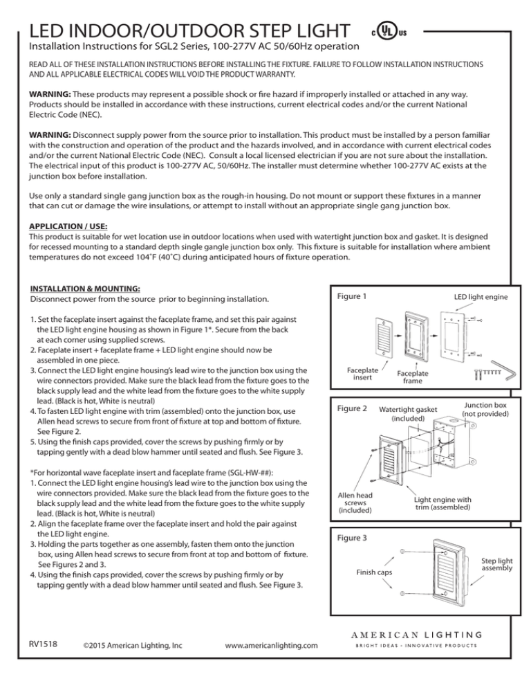
LED INDOOR/OUTDOOR STEP LIGHT Installation Instructions for SGL2 Series, 100-277V AC 50/60Hz operation READ ALL OF THESE INSTALLATION INSTRUCTIONS BEFORE INSTALLING THE FIXTURE. FAILURE TO FOLLOW INSTALLATION INSTRUCTIONS AND ALL APPLICABLE ELECTRICAL CODES WILL VOID THE PRODUCT WARRANTY. WARNING: These products may represent a possible shock or fire hazard if improperly installed or attached in any way. Products should be installed in accordance with these instructions, current electrical codes and/or the current National Electric Code (NEC). WARNING: Disconnect supply power from the source prior to installation. This product must be installed by a person familiar with the construction and operation of the product and the hazards involved, and in accordance with current electrical codes and/or the current National Electric Code (NEC). Consult a local licensed electrician if you are not sure about the installation. The electrical input of this product is 100-277V AC, 50/60Hz. The installer must determine whether 100-277V AC exists at the junction box before installation. Use only a standard single gang junction box as the rough-in housing. Do not mount or support these fixtures in a manner that can cut or damage the wire insulations, or attempt to install without an appropriate single gang junction box. APPLICATION / USE: This product is suitable for wet location use in outdoor locations when used with watertight junction box and gasket. It is designed for recessed mounting to a standard depth single gangle junction box only. This fixture is suitable for installation where ambient temperatures do not exceed 104˚F (40˚C) during anticipated hours of fixture operation. INSTALLATION & MOUNTING: Disconnect power from the source prior to beginning installation. 1. Set the faceplate insert against the faceplate frame, and set this pair against the LED light engine housing as shown in Figure 1*. Secure from the back at each corner using supplied screws. 2. Faceplate insert + faceplate frame + LED light engine should now be assembled in one piece. 3. Connect the LED light engine housing’s lead wire to the junction box using the wire connectors provided. Make sure the black lead from the fixture goes to the black supply lead and the white lead from the fixture goes to the white supply lead. (Black is hot, White is neutral) 4. To fasten LED light engine with trim (assembled) onto the junction box, use Allen head screws to secure from front of fixture at top and bottom of fixture. See Figure 2. 5. Using the finish caps provided, cover the screws by pushing firmly or by tapping gently with a dead blow hammer until seated and flush. See Figure 3. *For horizontal wave faceplate insert and faceplate frame (SGL-HW-##): 1. Connect the LED light engine housing’s lead wire to the junction box using the wire connectors provided. Make sure the black lead from the fixture goes to the black supply lead and the white lead from the fixture goes to the white supply lead. (Black is hot, White is neutral) 2. Align the faceplate frame over the faceplate insert and hold the pair against the LED light engine. 3. Holding the parts together as one assembly, fasten them onto the junction box, using Allen head screws to secure from front at top and bottom of fixture. See Figures 2 and 3. 4. Using the finish caps provided, cover the screws by pushing firmly or by tapping gently with a dead blow hammer until seated and flush. See Figure 3. RV1518 ©2015 American Lighting, Inc www.americanlighting.com Figure 1 LED light engine Faceplate insert Figure 2 Faceplate frame Watertight gasket (included) Allen head screws (included) Junction box (not provided) Light engine with trim (assembled) Figure 3 Finish caps Step light assembly

