Product
Specification
108-37078
Rev. E
10-Jun-2013
HEADER ASSY 35/47 POSN.
Design Objectives
The product described in this document has not been fully tested to insure
conformance to the requirements outlined below. Therefore, Tyco Electronics Brazil
makes no representation or warranty, express or implied, that the product will comply
with these requirements. Further, Tyco Electronics Brazil may change these
requirements based on the results of additional testing and evaluation.
Contact Tyco Engineering for further details.
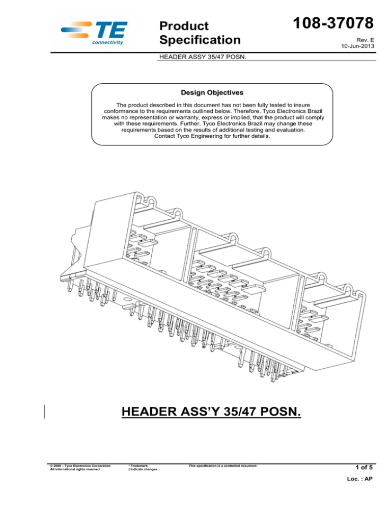
HEADER ASS’Y 35/47 POSN.
© 2009 – Tyco Electronics Corporation
All international rights reserved .
* Trademark
| Indicate changes
This specification is a controlled document .
1 of 5
Loc. : AP
108-37078
HEADER ASSY 35/47 POSN.
1.
SCOPE
1.1
Content
This specification covers the performance requirements and test methods of Header
Assembly, 35/47 Posn.
1.2
TE Part Number
"Trade Mark” Description
1989538-1
1989538-6
HEADER ASS’Y 47 POSN.
HEADER ASS’Y 35 POSN.
Qualification
When all the tests have been successfully performed on the subject product line, the product is
qualified according to the present specification.
2.
APPLICABLE DOCUMENTS
The following documents form a part of this specification to the extent specified herein. In the event of
conflict between the requirements of this specification and product drawing, the product drawing shall
take precedence. In the event of conflict between the requirements of this specification and the
referenced documents, this specification shall take precedence.
2.1 Tyco Electronics Documents
a)
109-1: General Requirements for Test Specifications;
b) 109-11:Solderability Dip Test
2.2 Other Documents
a)
b)
ISO 16750-1: Environmental conditions and testing for electrical and electronic equipment – General;
ISO 16750-2: Environmental conditions and testing for electrical and electronic equipment – Electrical
loads;
c)
ISO 16750-3: Environmental conditions and testing for electrical and electronic equipment – Mechanical
loads;
d)
ISO 16750-4: Environmental conditions and testing for electrical and electronic equipment – Climatic
loads;
e)
f)
g)
h)
i)
3.
ISO 16750-5: Environmental conditions and testing for electrical and electronic equipment – Chemical
loads;
MT.BDS2/012: Environmental conditions and testing for electrical and electronic equipment – Buses;
DBL 5420: Supply specification – Plastics Insulation parts for Electrical low tension applications;
DIN 46225: Stamped terminals with embrace of the insulation for insulated cables;
VW 801 01: Unidades Funcionais Elétricas e Eletrônicas em Veículos
REQUIREMENTS
3.1 Design and Construction
Products shall be of the design, construction and physical dimensions specified on the applicable
drawings.
3.2 Materials and Finish
• HEADER, 35/47 POSN
• PIN GUIDE
• TABS
Revision “E”
PPA + GF 33% - Black;
PPA + GF 33% - Black;
BRASS, TIN PLATED
2 of 5
108-37078
HEADER ASSY 35/47 POSN.
3.3 Current Carrying Capacity and maximum operating voltage
a) Individual Continuous Current Carrying Capacity at 70°C for single loaded terminal when used
with Tyco Electronics female terminals. For other loads, please consult Tyco Electronics
Engineering Department:
- Micro Power Timer : 10A
- Junior Power Timer :20A
- Std Power Timer :30ª
b) Voltage 12 VDC.
3.4 Temperature rating
Temperature rating shall be within the range specified as following:
• -30º / +70ºC.
3.5 Sealing class
Sealing rating shall be within the range specified as following:
•
4.
Not sealed
GENERAL TEST CONDITIONS
Unless otherwise specified, all measurements and tests shall be performed at a room temperature of
23 ± 5ºC and a relative humidity of 25 to 75%.
The test voltages shall be in accordance with table 1:
Test Voltage
UA
UB
Volts System (V)
14
(±0,2)
12
(±0,2)
Table 1: Test Voltages
UA = engine /alternator operative;
UB = battery voltage
5.
TEST REQUIREMENTS AND PROCEDURE SUMMARY
TEST DESCRIPTION
5.1
Visual
examination
TEST DESCRIPTION
PRODUCT EXAMINATION
PROCEDURE
Product shall be in accordance with
the requirements of production
drawing
Engaging
connector
force
Operation speed : 50mm/min
5.3
Disengage
connector
force
Apply an axial load to unmate tab/rec
connectors at a rate of 50
mm/minute, with the connector lock
engaged.
Revision “E”
Visual, dimensional and functional check.
MECHANICAL REQUIREMENTS
PROCEDURE
5.2
REQUIREMENT
REQUIREMENT
The mating force shall be:
Connector 12 Pos. ≤ 100N;
Connector 23 Pos. ≤ 180N
For Headers: >150 N.
3 of 5
108-37078
HEADER ASSY 35/47 POSN.
5.4
5.5
Free fall (Drop
test)
Subject Header Ass’y to a drop of
1,0m height on concrete ground or
steel plate. Shall be tested in all six
spatial directions.
Hidden damage is not permitted. Minor
damage of the Header Ass’y is permitted
as long as this does not affect the
performance.
Header Pin
Retention
Measurement shall be taken in both
directions if possible, i.e.force to
push the pin longitudinally through
the connector,and to pull it out as if
removing a female plug from the
header.Pressure or tension must be
applied parallel with the axis of the
pin to achieve accurate results
This test determines the retention of the
male terminal. The minimum force
required to displace the pin longitudinally
in either direction shall meet the values
specified below:
Terminal 1,5mm – 55N min.
Terminal 2,8mm – 80N min.
Terminal 4,8mm – 120N min.
TEST DESCRIPTION
ELECTRICAL REQUIREMENTS
PROCEDURE
REQUIREMENT
5.6
Dieletric
Strength
Apply 500V AC, 60 or 50 Hz for 2
minutes between any two conductive
parts designed to operate at different
potentials.
Determine the leakage current.
This test ensures that any circuit is
sufficiently isolated from adjacent circuits.
The leakage current shall not exceed 1
mA.
5.7
Insulation
Resistance
The insulation resistance shall not be
less than 10 MOhm at 500 VDC.
This test ensures that the material used for
the housing is sufficient for insulating the
current in the EDB with any surrounding
part
Voltage Drop
Terminal 1,5mm 10,0 mΩ
Terminal 2,8mm 5,0 mΩ
Terminal 4,8mm 3,02 mΩ
5.8
TEST DESCRIPTION
This test determines the voltage drop
associated with the electrical resistance of
the conductor crimp and contact interface
regions at nominal current conditions
ENVIRONMENTAL REQUIREMENTS
PROCEDURE
REQUIREMENT
5.9
Corrosion, salt
spray
Subject Header Ass’y assembled to
96 hrs according to ASTM B117
No base metal corrosion;
5.10
Resistance to
low
temperature
Connectors mated samples shall be
kept at -40°C for 2h, then the
samples shall be brought at 0°C in 3’
max and left for thermal stabilization.
Unmate and remate the samples.
No breakage of plastic parts;
5.11
Accelerated
Ageing
On mated connectors,which shall be
submitted to the following cumulative
tests:
A- 50 cycles with
thermal shock:
3 h at + 70°C±2°C
3 h at - 30°C±2°C
Transition time 180s
B- 10 cycles without
shock
2 h at + 70°C±2°C
2 h at – 30°C±2°C
Transition time 2 h
No deformation or cracking of the plastic
parts(change of colour is allowed)
5.12
Soldability
See TE spec 109-11-5
See TE spec 109-11
Note : The tests 5.1; 5.4; 5.5; 5.6; 5.7; 5.12 are referenced to the Header and they are tested by Tyco
Electronics.
The other tests are dependents of the counter-part (Receptacle housing) and they are not guaranteed
by Tyco Electronics.
Revision “E”
4 of 5
108-37078
HEADER ASSY 35/47 POSN.
6.
TEST SEQUENCE
Test Group and Sequence (a)
Item
Description
A
B
C
D
1, 4 1,3 1, 3 1,5
E
F
G
1,3 1, 3 1,3
H
Qty of
samples
I
5.1
Visual examination
1,3 1, 3
5.2
Engaging connector force
2
6
5.3
Disengage connector force
3
6
5.4
Free Fall Drop Test
5.5
Header Pin Retention
5.6
Dieletric strength
5.7
Insulation Resistance
5.8
Voltage Drop
5.9
Corrosion Salt Spray
5.10
Resistance to low temperature
5.11
Accelerated ageing
5.12
Soldability
2
20
6
2
6
2
6
2
6
2,4
6
3
6
2
6
2
6
2
6
(a) Numbers indicate sequence in which tests are performed
Table 2 – Test Sequence
7.
GENERAL TEST CONDITION
According to VW 801 01, must be tested at least 6 samples.
Rev.
B
C
D
E
Date
01-Apr-2009
13-May-2009
30-Jun-2009
10-Jun-2013
Revision “E”
History
Description
Item 5. – added Test Voltage Drop
Item 5.2 - change requirements
Changed Item 5.5
Changed raw material; added new dash number and changed item 5.2
Prepared
M.Ogawa
M.Ogawa
M.Ogawa
G. Oliveira
Approved
A.Metzker
A.Metzker
A.Metzker
D.Oliveira
5 of 5


