QO® and QOU Miniature QOU Miniature Circuit Breakers and QYU Supplementary Protectors
Circuit Breakers
Class 720 / Refer to Catalog 0730CT9801
www.schneider-electric.us
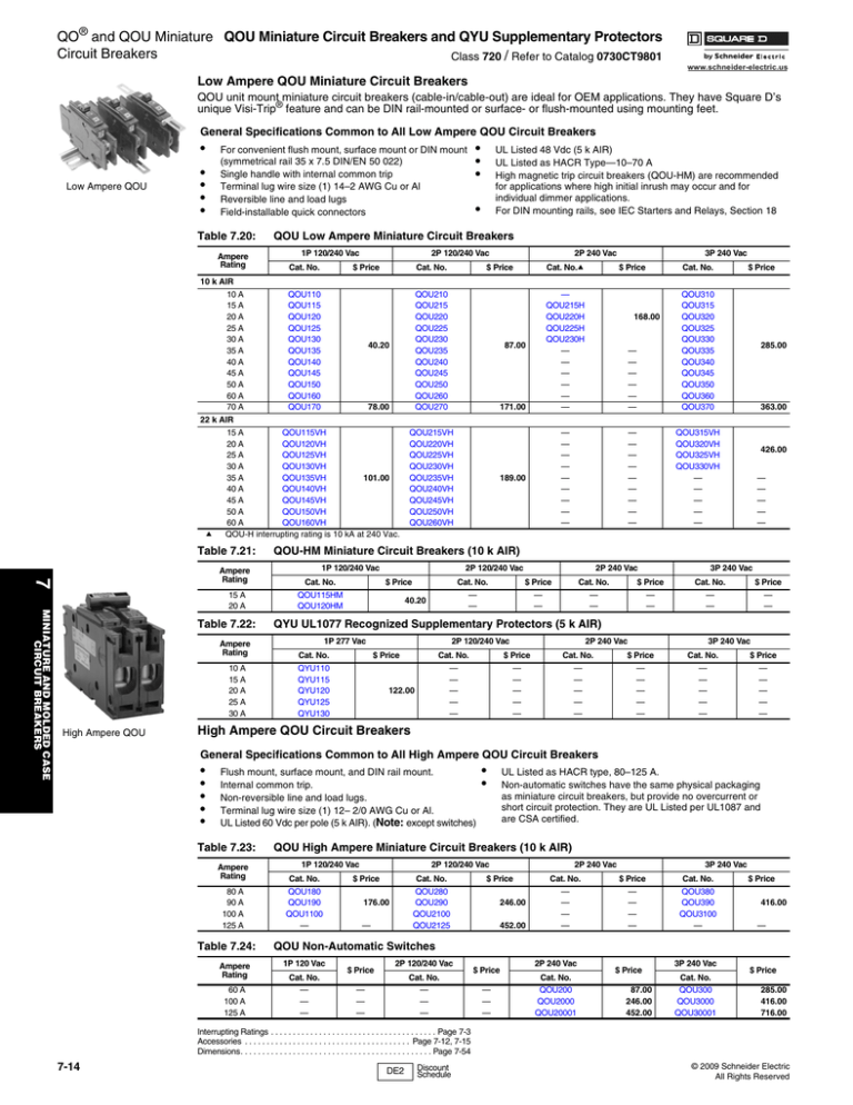
Low Ampere QOU Miniature Circuit Breakers
QOU unit mount miniature circuit breakers (cable-in/cable-out) are ideal for OEM applications. They have Square D’s
unique Visi-Trip® feature and can be DIN rail-mounted or surface- or flush-mounted using mounting feet.
General Specifications Common to All Low Ampere QOU Circuit Breakers
•
Low Ampere QOU
•
•
•
•
For convenient flush mount, surface mount or DIN mount
(symmetrical rail 35 x 7.5 DIN/EN 50 022)
Single handle with internal common trip
Terminal lug wire size (1) 14–2 AWG Cu or Al
Reversible line and load lugs
Field-installable quick connectors
Table 7.20:
Ampere
Rating
7
Ampere
Rating
MINIATURE AND MOLDED CASE
CIRCUIT BREAKERS
15 A
20 A
Table 7.22:
Ampere
Rating
10 A
15 A
20 A
25 A
30 A
High Ampere QOU
UL Listed 48 Vdc (5 k AIR)
UL Listed as HACR Type—10–70 A
High magnetic trip circuit breakers (QOU-HM) are recommended
for applications where high initial inrush may occur and for
individual dimmer applications.
For DIN mounting rails, see IEC Starters and Relays, Section 18
•
QOU Low Ampere Miniature Circuit Breakers
1P 120/240 Vac
Cat. No.
2P 120/240 Vac
$ Price
Cat. No.
10 k AIR
10 A
QOU110
15 A
QOU115
20 A
QOU120
25 A
QOU125
30 A
QOU130
40.20
35 A
QOU135
40 A
QOU140
45 A
QOU145
50 A
QOU150
60 A
QOU160
70 A
QOU170
78.00
22 k AIR
15 A
QOU115VH
20 A
QOU120VH
25 A
QOU125VH
30 A
QOU130VH
35 A
QOU135VH
101.00
40 A
QOU140VH
45 A
QOU145VH
50 A
QOU150VH
60 A
QOU160VH
a
QOU-H interrupting rating is 10 kA at 240 Vac.
Table 7.21:
•
•
•
2P 240 Vac
$ Price
QOU210
QOU215
QOU220
QOU225
QOU230
QOU235
QOU240
QOU245
QOU250
QOU260
QOU270
Cat. No.a
87.00
171.00
QOU215VH
QOU220VH
QOU225VH
QOU230VH
QOU235VH
QOU240VH
QOU245VH
QOU250VH
QOU260VH
3P 240 Vac
$ Price
Cat. No.
—
QOU215H
QOU220H
QOU225H
QOU230H
—
—
—
—
—
—
—
—
—
—
—
—
QOU310
QOU315
QOU320
QOU325
QOU330
QOU335
QOU340
QOU345
QOU350
QOU360
QOU370
—
—
—
—
—
—
—
—
—
—
—
—
—
—
—
—
—
—
QOU315VH
QOU320VH
QOU325VH
QOU330VH
—
—
—
—
—
189.00
168.00
$ Price
285.00
363.00
426.00
—
—
—
—
—
QOU-HM Miniature Circuit Breakers (10 k AIR)
1P 120/240 Vac
Cat. No.
QOU115HM
QOU120HM
2P 120/240 Vac
$ Price
Cat. No.
—
—
40.20
2P 240 Vac
$ Price
—
—
Cat. No.
—
—
$ Price
—
—
3P 240 Vac
Cat. No.
—
—
$ Price
—
—
QYU UL1077 Recognized Supplementary Protectors (5 k AIR)
1P 277 Vac
Cat. No.
QYU110
QYU115
QYU120
QYU125
QYU130
2P 120/240 Vac
$ Price
Cat. No.
—
—
—
—
—
122.00
$ Price
—
—
—
—
—
2P 240 Vac
Cat. No.
—
—
—
—
—
$ Price
—
—
—
—
—
3P 240 Vac
Cat. No.
—
—
—
—
—
$ Price
—
—
—
—
—
High Ampere QOU Circuit Breakers
General Specifications Common to All High Ampere QOU Circuit Breakers
•
•
•
•
•
Flush mount, surface mount, and DIN rail mount.
Internal common trip.
Non-reversible line and load lugs.
Terminal lug wire size (1) 12– 2/0 AWG Cu or Al.
UL Listed 60 Vdc per pole (5 k AIR). (Note: except switches)
Table 7.23:
Ampere
Rating
80 A
90 A
100 A
125 A
Table 7.24:
Ampere
Rating
60 A
100 A
125 A
•
•
UL Listed as HACR type, 80–125 A.
Non-automatic switches have the same physical packaging
as miniature circuit breakers, but provide no overcurrent or
short circuit protection. They are UL Listed per UL1087 and
are CSA certified.
QOU High Ampere Miniature Circuit Breakers (10 k AIR)
1P 120/240 Vac
Cat. No.
QOU180
QOU190
QOU1100
—
2P 120/240 Vac
$ Price
Cat. No.
QOU280
QOU290
QOU2100
QOU2125
176.00
—
2P 240 Vac
$ Price
246.00
452.00
Cat. No.
—
—
—
—
3P 240 Vac
$ Price
—
—
—
—
Cat. No.
QOU380
QOU390
QOU3100
—
$ Price
416.00
—
QOU Non-Automatic Switches
1P 120 Vac
Cat. No.
—
—
—
$ Price
2P 120/240 Vac
Cat. No.
—
—
—
—
—
—
$ Price
—
—
—
2P 240 Vac
Cat. No.
QOU200
QOU2000
QOU20001
$ Price
87.00
246.00
452.00
3P 240 Vac
Cat. No.
QOU300
QOU3000
QOU30001
$ Price
285.00
416.00
716.00
Interrupting Ratings . . . . . . . . . . . . . . . . . . . . . . . . . . . . . . . . . . . . . . Page 7-3
Accessories . . . . . . . . . . . . . . . . . . . . . . . . . . . . . . . . . . . . . . Page 7-12, 7-15
Dimensions. . . . . . . . . . . . . . . . . . . . . . . . . . . . . . . . . . . . . . . . . . . . Page 7-54
7-14
DE2
Discount
Schedule
© 2009 Schneider Electric
All Rights Reserved
Selection Information
Miniature Circuit Breakers
Class 500, 600
www.schneider-electric.us
Multi 9™ Circuit Breakers and
Supplementary Protectors
—
—
—
QOM1-VH
QOM2-VH
—
—
QOU
QYUa
—
—
UL 489
C60N
UL1077
C60Nb
—
—
—
EDB
EGB
EJB
2
3
1
2
2
1
2
3
1
2
3,4
1
2
1
Current Range
10–100
10–30
50–125
100–225
0.5–35
0.5–35
0.5–35
0.5–63
1–63
1–63
0.5–40
0.5–40
15–70
—
1
10–125
C60H-DC
Number of Poles
10–100
Unit Mount
New!
Interrupting Ratings
120 Vac
10
10
10
—
22
22
10
—
—
10
10
10
—
—
25
UL/CSA
120/240 Vac
10
10
10
—
22
22
5
10
10
10
10
10
—
—
18
Rating
240 Vacc
—
—
10
—
—
—
5
10
10
10
10
10
—
—
18
(kA RMS)
277 Vac
—
—
—
5
—
—
—
—
—
5
5
5
—
—
18
(50/60 Hz)
480Y/277 Vac —
—
—
—
—
—
10
10
10
—
5
5
—
—
—
48 Vdc
5d
5d
5d
—
—
—
—
—
—
10
10
—
5
5
—
60 Vdc
5e
5e
5e
—
—
—
10
10
—
—
—
—
5
5
—
65 Vdc
—
—
—
—
—
—
—
—
—
10
10
—
5
5
—
DC Ratings
125 Vdc
—
—
—
—
—
—
—
10
—
—
10
—
5
5
—
250 Vdc
—
—
—
—
—
—
—
—
—
—
—
—
5
5
—
500 Vdc
—
—
—
—
—
—
—
—
—
—
—
—
—
5k
—
IEC 60947-2
240 Vac
—
—
—
—
—
—
20
20
20
10
10
10
20
10
20
(50/60 Hz)
415 Vac
—
—
—
—
—
—
—
10
10
—
5
5
—
—
10
Icu
Special Ratings
Fed. Specs
X
X
X
X
X
X
X
X
X
—
—
—
—
—
X
W-C-375B/GEN
Other Standard
HACR f
—
—
—
—
—
—
g
—
—
—
—
Accessories and Modifications
Shunt Trip
Xh
Xh
Xh
Xh
—
X h
X
X
X
X
X
X
X
X
X h
Undervoltage Trip
—
—
—
—
—
—
X
X
X
X
X
X
X
X
—
Auxiliary Switches
Xh
Xh
Xh
Xh
—
—
X
X
X
X
X
X
X
X
Xh
Alarm Switch
Xh
Xh
Xh
Xh
—
—
X
X
X
X
X
X
X
X
Xh
Handle Operators
—
—
—
—
—
—
X
X
X
X
X
X
X
X
—
Handle Padlock
X
X
X
X
X
X
X
X
X
X
X
X
X
X
X
Attachment
Trip System Type
Thermal-magnetic
X
X
X
X
X
X
X
X
X
X
X
X
X
X
X
Molded Case Switch
—
X
X
—
—
—
—
—
—
—
—
—
—
—
—
Dimensions (1P Unit Mount)
Dimensions
Height
4.05 (103)
5.09 (129)i 5.60 (142)i
4.21 (107)j
3.19 (81)
3.19 (81)
(1P Unit
Width
0.75 (19)
5.00 (127)i 5.07 (129)i
0.71 (18)
0.71 (18)
0.71 (18) 1.42 (36)
Mount)
Depth
2.92 (74)
3.47 (88)i 3.60 (91)i
2.76 (70)
2.76 (70)
2.56 (65)
in. (mm)
Pages
Pages 7-14
Pages 1-2
Pages 7-16 through 7-19
Note: All circuit breakers on this chart are UL Listed and CSA Certified unless otherwise noted.
1
—
2,3
1
2,3
25
25
25
18
18
—
—
—
—
—
—
—
65
35
35
35
—
—
—
—
—
—
—
—
65
65
65
35
35
—
—
—
—
—
—
—
100
65
65
65
—
—
—
—
—
—
—
—
100
100
100
65
65
—
—
—
—
—
—
—
—
—
—
—
—
X
X
X
X
X
HACR
X h
—
Xh
Xh
—
X h
—
Xh
Xh
—
X h
—
Xh
Xh
—
X h
—
Xh
Xh
—
X h
—
Xh
Xh
—
X
X
X
X
X
X
—
X
—
X
—
X
—
X
—
5.66 (144)
0.98 (25)
4.05 (103)
Page 9-17
QYU is a UL 1077 supplementary protector.
C60N are recognized components per UL 1077.
For information regarding 3Ø corner grounded systems see the Supplemental Digest.
1P and 2P, 10–70 A and 3P 10–60 A only.
QOU is UL Listed for 60 Vdc per pole 80–100 A, 1P; 80–125 A, 2P; and 70–100 A, 3P.
HACR on QOU 1P and 3P 15–100 A, 2P 15–125 A;
UL 489A for DC Telecom applications (1-pole only).
Factory-installed option only
QOM1 and QOM2 dimensions are for 2-pole unit.
480 V C60 height is 5.56 in. (141 mm).
2 poles must be wired in series for 500 Vdc.
© 2009 Schneider Electric
All Rights Reserved
7
a
b
c
d
e
f
g
h
i
j
k
—
2,3
MINIATURE AND MOLDED CASE
CIRCUIT BREAKERS
—
—
15–125
—
—
15–70
—
Bolt-on
15–125
Plug-on
EDB Circuit Breakers
15–70
Circuit
Breaker
Type
QOM1 and QOM2 Main
Circuit Breakers
15–125
QOU
Circuit Breakers
7-3
Dimensions and Shipping Weights
Miniature and Molded Case Circuit Breakers
www.schneider-electric.us
A
G
A
G
A
G
Table 7.140:
D
C
QO®, QOU, Multi 9TM Circuit Breakers
Circuit Breaker
Cat. No. Prefix
B E
B E
B E
Figure 1
Figure 3
Figure 2
A
G
A
G
B
A
G
A
G
QO-GFI, QO-PL
QO-EPD
Figure 5
Figure 4
A
G
B E
Figure 6
D
C
E
E
B
B E
QO, QOB
D
C
F
B E
Figure 7
QOU, QYU
Low Ampere
Figure 8
A
D
C
A
A
B
Figure 9
QO-PLPS
Circuit Breaker
Cat. No. Prefix
B E
Figure 10
Figure 11
Figure 12
7
D
A
A
MINIATURE AND MOLDED CASE
CIRCUIT BREAKERS
B
B
A
A
B
B
Figure 13
Figure 14
Figure 15
A
A
A
C
E
Figure 16
B
Figure 17
E
B
B
Figure 18
B
G
C
B E
B
Figure 19
Figure 20
C120
B
E
B
G
HH
F
G
—
—
—
—
—
—
—
—
5.00d
5.00d
5.00f
6.78
6.78
6.78
—
—
—
—
—
0.59
1.34
2.09
2.85
4.35
0.59
1.34
2.09
0.62
1.37
2.12
—
—
—
—
—
—
—
—
QB, QD, QG, QJ, Q4, FA, FI, KA, KC, KI, LA, LC, LI,
LE, LX, LXI, MA Circuit Breakers
Dimensions—Inches
D
E
F
G
H
2
3
1
2
3
22
23
21
22
23
6.47
6.47
6.00
6.00
6.00
3.00
4.50
1.50
3.00
4.50
3.02
3.02
3.16
3.16
3.16
3.93
3.93
4.13
4.13
4.13
g
g
0.44
0.44
0.44
4.25
4.25
5.13
5.13
5.13
—
1.50
1.50
—
1.50
—
0.75
—
—
0.75
FIL, KAL, KCL,
2&3
23
8.00
4.50
3.66 4.75 0.44
KHL, KIL
Q4L, LAL, LHL
2&3
23
11.00 6.00
4.06 5.84 0.88
LIL, LEL, LXL, LXIL, 2 & 3
24
11.86 7.50
5.48 6.74 0.55
LCL
MAL, MHL
2&3
23
14.00 9.00
4.53 6.50 1.66
g
Dimensions E are 1.59 in at ON end and 0.63 in at OFF end.
7.13
1.50
0.75
9.25
2.00
1.00
10.75
2.50
10.69
3.00
Frame Size
1.50
Shipping Weightsh
Approx. Shipping
Weight (Lbs.)
Approx. Shipping
Weight (Lbs.)
Frame Size
FAL, FHL 1P
2
KIL
9
FAL, FHL 2P
3
LAL, LHL
15
FAL, FHL 3P
5
LEL, LIL, LXL, LXIL, LCL
25
FIL
8
Q4L
15
QB, QD, QG, QJ
4
MAL, MHL
34
KAL, KHL
7
h
E
E
2.25
2.25
2.25
3.78
3.78
2.25
2.25
2.25
2.25
2.25
2.25
2.25
2.25
2.25
1.77
1.77
1.77
1.77
—
C
C60
D
D
B
Table 7.142:
A
C
A
FAL, FHL
QOU
High Ampere
B
Fig.
No.
B F
B E
A
Poles
QB, QD,
QG, QJ
B E
Dimensions—Inches
Fig.
No.
1
1
0.75 3.00a 2.31
2.91
QO, QOB
2
2
1.50 3.00a 2.31
2.91
3
3
2.25 3.00a 2.31
2.91
2
2
3.0
5.72
2.53
4.90
QOB-VH 150 A
QOB-VH 110–150 A
3
3
4.50
5.72
2.53
4.90
1
4
0.75 4.12b 2.31
2.91
QO-PL
QO-GFI
2
5
1.50 4.12b 2.31
2.91
QO-EPD
3
5
2.25 4.12b 2.31
2.91
1
6
0.75 4.05c 2.38
2.98
QOU
QYU
2
7
1.50 4.05c 2.38
2.98
Low Ampere
3
8
2.25 4.05d 2.38
2.98
1
10
0.75
4.45
2.37
2.96
QOU
2
11
1.50
4.45
2.37
2.96
High Ampere
3
12
2.25
4.45
2.37
2.96
1
13
0.71
3.19
1.73
2.76
2
14
1.42
3.19
1.73
2.76
Multi 9™ C60N
3
15
2.13
3.19
1.73
2.76
4
16
2.84
3.19
1.73
2.76
QO-PLPS Power Supply
2
9
1.45
4.35
2.42
3.11
a
35–70 A is 3.12 in; 80–100 A 2P and 70–100 A 3P are 3.50 in.
b
QO-PL is 4.55 in.
c
80–100 A 1P and 80–125 A 2P are 4.45 in
d
80–100 A 1P and 80–125 A 2P are 6.78 in.
e
70–100 A 4.45 in.
f
70–100 A is 6.78 in.
Table 7.141:
D
C
A
Poles
All weights are for 3P circuit breakers unless otherwise noted.
D
C
C/L
A F
C/L
A F
A F
E
E
Figure 21
Figure 22
B
G
E
D
C
Figure 23
E
A F
E
Figure 24
7-54
© 2009 Schneider Electric
All Rights Reserved


