EE 804 EE 805 - Harju Elekter
advertisement

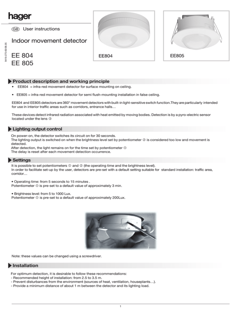
9416-275-00/06.05 GB User instructions Indoor movement detector EE 804 EE 805 EE805 EE804 Product description and working principle • EE804 = infra-red movement detector for surface mounting on ceiling. • EE805 = infra-red movement detector for semi flush-mounting installation in false ceiling. EE804 and EE805 detectors are 360° movement detectors with built-in light-sensitive switch function.They are particularly intended for use in interior traffic areas such as corridors, entrance halls… These devices detect infrared radiation associated with heat emitted by moving bodies. Detection is by a pyro-electric sensor located under the lens e Lighting output control On power-on, the detector switches its circuit on for 30 seconds. The lighting output is switched on when the brightness level set by potentiometer d is considered too low and movement is detected. After detection, the light remains on for the time set by potentiometer c The delay is reset after each movement detection occurrence. Settings It is possible to set potentiometers c and d (the operating time and the brightness level). In order to facilitate set-up by the user, detectors are pre-set with a default setting suitable for standard installation: traffic area, corridor… • Operating time: from 5 seconds to 15 minutes . Potentiometer c is pre-set to a default value of approximately 3 min. • Brightness level: from 5 to 1000 Lux. Potentiometer c is pre-set to a default value of approximately 200Lux. Note: these values can be changed using a screwdriver. Installation For optimum detection, it is desirable to follow these recommendations: - Recommended height of installation: from 2.5 to 3.5 m. - Prevent disturbances from the environment (sources of heat, ventilation, houseplants…). - Provide a minimum distance of about 1 m between the detector and its lighting load. 1 Drawing of EE804 Detection lens Knock-out Protective cover Drawing of EE805 Fixing springs Detection lens 2,5 m Operating time potentiometer 6 Brightness level potentiometer m 6m Troubleshooting • Unwanted switch-on of lighting point: check that the detector is not close to a heat source, or under a direct light, above a ventilation grill… • The range of the detector is too short: check that detector's installation height and location are optimal. 2 Mounting of EE804 (surface mouting) Ceiling Flush-mounting box 1) Unscrew the protecting cover f 2) Cable the detector according to the recommended connection diagrams. 3) Fix the detector with the screws provided (ø 4 mm). 4) Settings: set potentiometers c and d according to the desired values if different from preset default values. 5) Re-fix the protecting cover f If the supply cables are coming into the detector in surface mounted trunking, section h can be removed easily. Mounting of EE805 (semi flush-mounting version) Ceiling e = ceiling thickness 5 < e < 20 mm ø 75 1) Cut out a 75 mm diameter hole using a hole saw. 2) Cable the detector according to the recommended connection diagrams. Then clip on the transparent connector block/protecting cover provided. 3) Set potentiometers c and d according to the desired values if different from preset default values 4) Fix the detector by pushing both springs g upward then insert it in the hole cut out previously. Note: the thickness of the support ceiling (e) must be within 5 to 20 mm range. 3 Connections Operation Auto/Off ref. EE804 (surface mount) N Operation Auto/On ref. EE804 (surface mount) N L L Earth Green/yellow Bridging N 230 V~ L S1 Bridging Switch Earth Green/yellow N 230 V~ L S1 Switch S1 Open = stop S1 Closed = automatic mode S1 open = automatic mode S1 closed = permanent switch on Operation Auto/Off ref. EE805 (flush mount) L N Switch Earth Green/yellow Bridging N 230 V~ L N Earth Green/yellow S1 L Operation Auto/On ref. EE805 (flush mount) Bridging N 230 V~ L S1 Switch S1 open = automatic mode S1 closed = permanent switch on S1 Open = stop S1 Closed = automatic mode S1 Lighting loads IMPORTANT NOTE! When using with unspecified loads it is important to use a contactor to switch the load. 10 A AC1 230 V~ Incandescent, Halogen 230 V 1000 W Halogen ELV (12 or 24 V) via ferromagnetic or electronic transformer 500 VA Fluorescent compact 10 x 20 W Parallel non compensated fluorescent tubes 1000 W Electronic ballast 8 x 58 W Parallel compensated fluorescent tubes 174W (20µF) Technical features Electric characteristics Supply voltage: Consumption with no load: 230V 50Hz 1.2W Functional characteristics Lighting output operating time: Brightness level: Recommended installation height: Detection range of 3m approximately (installed product height: 2.5m) Fixing accessories: Products in parallel: 5 s —> 15 min 5 —> 1000 Lux 2.5m —> 3.5m screws (ø 4 mm) pegs, protecting cover/connector block Yes Environment Operating T °: Storage T °: Class of insulation: IK : Index of protection : Fire resistance: Standards: Connection capacity 1mm 2 —> 2,5 mm 2 0 °C —> +45 °C -20 °C —> +60 °C II 03 IP21 750°C IEC 60669-1 and IEC 60669-2-1 1mm 2 —> 2,5 mm 2 4


