The CN Tower
The world’s tallest freestanding
structure is a functional landmark in
concrete
C
onstructing a single facility adequate for all of To ro nto’s radio and TV requirements dictated the great
height of the CN Communications Tower. An elevation of
1100 feet was needed to clear all Toronto area obstacles
for microwave re c e i ve r s. Above that height a 350-foot
separation was required between the receivers and the
UHF/VHF and FM antennas, which in turn had to be
spread out over a 335-foot antenna mast. These and other design considerations led to a slender, tapering beauty in concrete, and a record height for a freestanding
structure—1815 feet 5 inches. The record was previously
held by the 1761.89-foot Ostankino Tower for radio and
STATISTICS
Height: 1815 feet 5 inches
Dimension at base: 167 feet (side of triangle)
Variation of concrete from plumb: 1.1 inches
Sky pod diameter: 100 to 140 feet
height: 7 levels
floor space: 70,000 square feet
Total weight: 130,000 tons
Concrete: 53,000 cubic yards
Post-tensioned steel: 80 miles
Reinforcing steel: 5000 tons
Estimated sway resistance in 120-mph winds with
200-mph gusts: antenna—31⁄2 feet from center
space deck—11⁄2 feet from center
skypod—9 inches from center
Broadcast facility”* current users:
6 television broadcasters
8 FM broadcasters
7 microwave users
* Includes UHF, VHF and cable television, FM radio, microwave telecommunications, and local point-to-point and
mobile systems
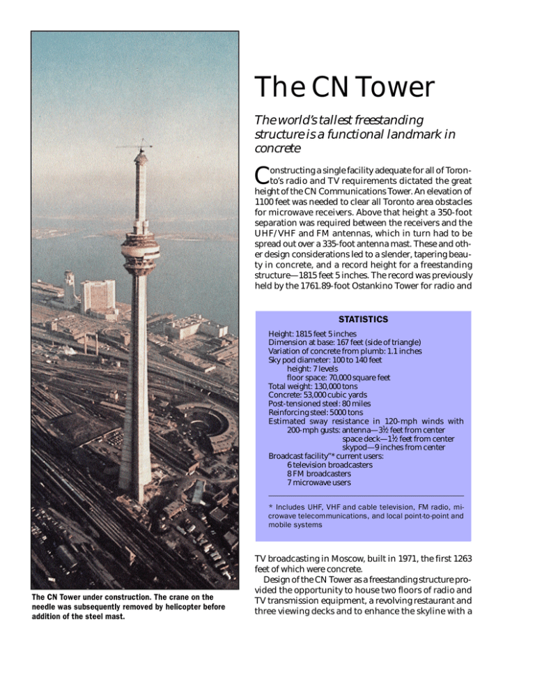
The CN Tower under construction. The crane on the
needle was subsequently removed by helicopter before
addition of the steel mast.
TV broadcasting in Moscow, built in 1971, the first 1263
feet of which were concrete.
Design of the CN Tower as a freestanding structure provided the opportunity to house two floors of radio and
TV transmission equipment, a revolving restaurant and
three viewing decks and to enhance the skyline with a
striking monument and navigational aid. From the top
deck, on a clear day, one can view the landscape as far
as 100 miles away.
Foundation
Findings from numerous pictures and test samples
taken as deep as 100 feet in four 30-foot-diameter holes
led to design of a Y-shaped foundation resting on shale
at a depth of about 50 feet and capable of both supporting the tower weight and resisting the great pre s s u re s
induced by wind. Since the water table was only 19 feet
down, the area had to be dewatered before excavation
and during construction of the foundation. Post-tensioning cables crisscrossing the Y prevent cracking. Nine
caverns within the foundation provided sheltered work
space and means of anchoring the vertical tendons of
the tower when post-tensioned.
Slipforming
A Y-shaped slipform accommodated the full dimensions of the base of the concrete tower. As the slipform
rose the end portions were jacked steadily inward and
the protruding ends of the sides were periodically cut
off. The tendency of the deck to rotate in response to the
e a rt h’s rotation was monitored every 2 hours by optical
plumb instruments on the slipform wings and the twisting was overcome by adjustment of three cables anchored to points on the walls below. A 250-pound steel
bob suspended from the slipform deck down through
the tower core into an oil bath provided readings for adjusting the plumb. Curing in winter was provided by a
heater deck below the finishing deck, followed by an insulated skirt, and by hot air within the core.
Concrete testing
With the monumental tower rising 20 feet per working
day, the builders were not comfortable to wait 1 to 4
weeks to assure themselves that 7- or 28-day concrete
strengths had been met. For the first time on a project of
any magnitude they boldly adopted a relatively new accelerated strength test based on autogenous curing. Using Type I and Type IV portland cements, singly or in
combination as required by weather, they achieved excellent strength control with 2-day tests. Cores taken at
ages greater than 28 days showed strengths between
6000 and 8000 psi.
Post-tensioning the tower
CN Tower configuration shows space deck at top of
slipformed concrete, 1465 feet above base. Top of antenna
mast at 1815 feet makes this the world’s tallest
freestanding structure.
Selection of a fully post-tensioned construction instead of reinforced or partially post-tensioned concrete
was made early in the design process. The fully post-tensioned structure will remain essentially uncracked at all
loads. This is important for a tower which will be exposed to great changes in temperature and humidity as
well as chemically aggressive air. Post-tensioning also
contributed to economy of materials, reducing the foundation requirements and permitting the walls of the
hexagonal core to be only about 24 inches thick.
Principal post-tensioning consists of 144 cables of various lengths. From the terminal heights of the post-tensioning ducts at 180, 560, 1122, 1255, 1370, and 1480 feet,
the high-strength 270,000-psi prestressing steel tendons
were fed from the slipform deck. When any duct became
unusable from plugging, damage to tendons or other
cause, one of the small number of spare ducts installed
for such exigencies was utilized. The longest tendons
stretched 9 feet 2 inches during tensioning. Cold weather precluded grouting of ducts containing tendons posttensioned in the winter. Corrosion of these tendons was
prevented by steadily blowing oil-free dry air up through
the ducts until summer.
Pod
The seven-level pod beginning at a height of about
1100 feet was built with six formwork sections of steel
box trusses, wood forms and reinforcing steel. These
were raised, after slipforming had been completed, by
open-faced climbing jacks located on a temporary structural steel frame at the top of the tower. With this formwork were cast 12 triangular concrete brackets that support the pod as well as the floor and wall concrete work
of the pod itself. The concrete floor cast just above the
brackets includes a ring beam that is a 12-sided polygon,
post-tensioned circumferentially to resist radial loads.
Antenna mast
A light tower crane was used to assemble the slipform,
then was lifted along with the slipform and handled materials on the slipform deck. After the remnants of the
slipform, which had diminished in size as it rose, were
dismantled and lowered, the crane remained in place to
raise the forms and concrete for casting in place the 16foot-high beam that supports the antenna mast. The
crane finally lifted the 12-foot-high steel base section of
the steel antenna mast before being taken down in eight
sections by a helicopter.
The helicopter then lifted the 39 mast sections into
place. A total of 55 helicopter construction flights were
made in 31⁄2 weeks, saving about 5 months construction
time. The mast sections, pentagonal cans varying from
31⁄2 to 20 feet high, were assembled by bolting. Inside the
mast are specially designed hula-hoop dampers tuned
to different frequencies to counter motion of the mast
from wind. Over the surface of the mast are mounted the
many antennas that serve the Toronto area.
A tower to be proud of
As the most unusual element of the skyline, the CN
Tower must inevitably become associated with Toronto
in people’s minds. Designed to resist the projected 1000year-frequency wind of 130 miles an hour with a factor
of safety of 2, it should long serve its purpose. As to serving the originally conceived purpose, Toronto and a
great surrounding area now enjoy what is probably the
best broadcast reception in the world.
Credits
Owner: CN Tower Ltd., Toronto
Architects: John Andrews International/Roger Du Toit; The
Webb Zerafa Menkes Housden Partnership, Toronto
Structural Consultants: Nicolet Carrier Dressel and Associates Ltd., Montreal
Manager Contractor: Foundation Company of Canada,
Toronto
PUBLICATION #C830125
Copyright © 1983, The Aberdeen Group
All rights reserved


