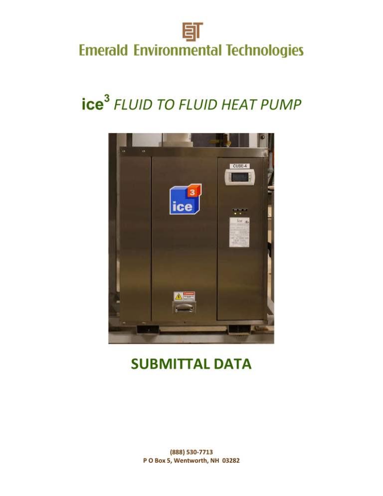
ice 3 FLUID TO FLUID HEAT PUMP SUBMITTAL DATA
advertisement

ice3 FLUID TO FLUID HEAT PUMP SUBMITTAL DATA (888) 530-7713 P O Box 5, Wentworth, NH 03282 Rev.3 (5-30-14) ice3, IC-2040 Fluid-to-Fluid R-410a Heat Pump Engineering Guide Specifications General Notes: a. The liquid source fluid-to-fluid heat pump shall be a single packaged non-reversing heating / cooling unit containing an internal refrigerant by water subcooling heat exchanger b. c. d. e. for preheating non potable water (such as an ice resurfacer). The unit shall be listed by a nationally recognized safety testing laboratory or agency, such as ETL. Testing shall be equal to CSA C22-2 or UL 427. The IC-2040 liquid source fluid-to-fluid heat pump unit as manufactured by Emerald Environmental Technologies, shall be designed to operate with evaporator entering liquid temperatures between 10°F (-12°C) and 70°F (21°C), and condenser entering liquid temperatures between 50°F (10°C) and 110°F (43°C). The evaporator entering fluid temperature must be lower than the condenser entering fluid temperature. Each unit shall be run-tested at the factory. Each unit shall be pallet mounted and stretch wrapped for shipping. Refrigerant Circuit: a. All units shall contain a sealed refrigerant circuit including a hermetically sealed scroll compressor with internal check valve, unidirectional electronically controlled thermal expansion valve assembly, two (2) stainless brazed plate fluid to refrigerant heat exchangers, factoryinstalled high and low pressure safety switches and service ports and a liquid line filter-drier. b. The refrigerant circuit shall utilize the tight closing electronic expansion valve to prevent migration of refrigerant to the evaporator when the compressor is not operating. c. Low-pressure lockout switch shall be automatic reset with interruption to compressor contactor power supply. d. High-pressure lockout switch shall be manual reset. e. The electronic thermal expansion valve assembly shall provide proper superheat over the liquid temperature range with minimal "hunting". The electronic thermal expansion valve shall be designed for single direction refrigerant flow. Bi-directional valves shall not be permitted. f. Externally mounted pressure controlled fluid regulating flow valves are not acceptable. g. The fluid to refrigerant evaporator and refrigerant suction lines shall be insulated with 3/4” (13mm) thick closed cell foam insulation (Armaflex) to prevent condensation at low liquid temperatures. h. Compressor shall be designed for refrigeration duty, with internal isolation and mounted on rubber vibration isolators. Compressor shall be manufactured with oil-sight glass. i. Compressor motor shall have internal motor protection and shall be three phase. Rev.3 (5-30-14) j. Compressor shall be designed for use with R410A refrigerant. Refrigerant piping shall be connected to compressor through a vibration isolator to permit absorption of compressor vibration and start-up torque without stress on piping. k. Refrigerant piping shall be clamped and supported to minimize vibration and prevent stress cracking. l. The liquid to refrigerant heat exchangers shall be brazed plate type constructed with type 316 stainless steel plates and brazed with copper. The heat exchangers shall be designed for minimum operation from -321°F (-196°C) to 350°f (177°C), and be capable of withstanding 650 PSIG (4480kPa) working pressure on liquid and refrigerant sides. Heat exchangers shall be manufactured with built in refrigerant distributor tube with calibrated orifices to distribute gas evenly throughout heat exchanger, and be designed for use with R410A refrigerant. m. Each unit shall be factory run tested for a minimum of two hours under actual load conditions, including: - Amperage and voltage draw Refrigerant Pressures Sight Glass Status Operation and Verification of High/Low Pressure Controls Entering and Leaving Fluid Temperatures for Condenser, Evaporator and Subcooler Superheat Measurement Operation of Compressor Overload Protection Electrical: a. Controls and safety devices will be factory wired and mounted within the unit. b. Controls shall include digital controller, expansion device controller for electronic EXV, user interface, compressor contactor, 24 VAC control circuit, built-in fuse protection, anti-rotation protection and voltage/loss of phase protection. c. Electrical circuit shall include fault light indicator light and green running indicator light on outside of cabinet, and shall include an "on-off-auto" selector switch mounted inside the heat pump cabinet. d. The digital controls can be provided with optional BACnet and or Modbus cards for remote BMS control. e. The system can be provided with a full digital control system to act as a global controller. Electrical Specifications Voltage/Phase/Hz 460/3/60 575/3/60 Compressor RLA 53.0 42.0 LRA 290 232 Total Unit FLA 61.9 50.0 Minimum Circuit Ampacity 77.3 62.5 Maximum Fuse Size 140 113 Rev.3 (5-30-14) Fluid Piping: a. Evaporator and Condenser supply and return fluid connections shall be 2” MPT threaded fittings. b. Non potable water connections to the subcooling heat exchanger shall be 3/4” sweat to a provided ball valve. c. All Fluid piping shall be insulated by customer on site to prevent condensation at low liquid temperatures. d. Pressure/temperature ports shall be included on both condenser and evaporator fluid inlets and outlets. e. Each unit shall be factory run-tested for a minimum of two hours under actual load conditions. A copy of the run test shall include: f. Amperage and voltage draw Refrigerant pressures Sight glass status Operation and verification of high and low pressure controls Entering and leaving fluid temperatures for condenser and evaporator Superheat measurement A copy of the run-test shall be included in the installation manual shipped with the unit and a copy shall be maintained at the factory. Casing and Cabinet: a. The cabinet shall be fabricated from 16 gauge polished stainless steel. The cabinet shall have removable access panels on three sides, and a hinged access door over the electrical cabinet. b. The interior shall be insulated with ½” (13 mm) thick multi-density, coated glass fiber, with edges sealed or tucked under flanges. c. All units shall have 7/8" (22 mm) and 1 1/8" (29 mm) knockouts for entrance of low and high voltage wiring. d. Cabinet dimensions shall be less than 31" (788 mm) in width or depth to permit units to be easily moved through a standard size door. e. The unit shall be built on a 14 gauge stainless steel baseplate. The cabinet shall be built to allow service access to the internal components. The baseplate shall have skids to allow for forklift handling the unit and to sit the unit on the floor or mount to a stand. This design minimizes the physical space requirements of the units. Optional Mounting Rack: Unit(s) can be mounted on a painted welded carbon steel rack supplied by the manufacturer. Rev.3 (5-30-14) Warranty Information: Emerald Environmental Technologies has great confidence in the quality of the ice3 unit and this is reflected in our warranty. The unit shall be warranted by the manufacturer against defects in materials and workmanship for a period of one (1) year from date of delivery to original purchaser-user including the compressor, condenser, evaporator and expansion valve. The stainless steel cabinet shall be warranted for life against defect in materials and workmanship, excluding damage due to rough handling, abuse, accident or casualty loss, chlorine or salt air exposure, airborne contaminants or outdoor installation. Other warranty options are available, please contact manufacturer for details. FIELD PIPING SUPPLIED BY OTHERS PIPING ZONE FOR UNIT CONNECTIONS PIPING ZONE FOR UNIT CONNECTIONS 36” (915 mm) 24” (610 mm) SIDE SERVICE CLEARANCE IC-2040 SIDE SERVICE CLEARANCE IC-2040 24” (610 mm) 48” (1,220 mm) FRONT SERVICE CLEARANCE FRONT SERVICE CLEARANCE THIS AREA FOR LIFT ACCESS DATE: 12/22/11 MINIMUM CLEARANCE REQUIREMENTS MODEL: IC-2040 DRAWN: J.E.D. REV: 2 FIELD PIPING SUPPLIED BY OTHERS 12” (305 mm) TOP SERVICE CLEARANCE IC-2040 THIS AREA FOR LIFT ACCESS 96" (2440mm) FRONT SERVICE CLEARANCE IC-2040 PIPING ZONE FOR UNIT CONNECTIONS 48" (1220mm) 36” (915 mm) Side view MINIMUM CLEARANCE REQUIREMENTS MODEL: IC-2040 DATE: 3/12/13 DRAWN: J.E.D. REV: 2 480V. Pri. L1 L2 N 6 24V. Sec. 1A Control Fuse N 6 PWR Carel Pco5 6 27 G GO ID1 C1 N 6 HOA - Hand 6 ID2 FLT C1AS (1) 6 6 21 NO1 ID3 LPS SECM (1) HPS PM (1) C1 Run NO3 6 C4 ID5 CVB-ES 6 ID6 HVA-ES 6 ID7 HVB-ES 16 N NO4 CVB N NO5 HVA ID8 HOA - Auto B1 NTC T1 N CVA ID4 CVA-ES 6 17 NO2 N NO6 HVB B2 NTC T2 N NO7 Pump NTC T3 B3 NTC T4 B4 6 GND Legend: Carel EVD G GO N G P1 - SP DWG NO. IC2040-D2 VRef S1 NTC T5 S2 P2 - DP S3 1 2 4321 C1 – Compressor #1 Contactor C1AS – Compressor #1 contactor auxiliary switch CVA – Cold valve A (-ES – Endswitch in actuator) CVB – Cold valve B FLT – Fault indicator lamp HVA – Hot valve A HVB – Hot valve B HOA – Hand, off, or automatic selector HPS – Mechanical high pressure safety LPS – Mechanical low pressure safety P1 SP – Refrigerant suction pressure P2 DP – Refrigerant discharge pressure PWR – Control circuit power indicator PM – Phase monitor SECM – Bitzer SE compressor module T1- Entering evaporator temperature T2 – Entering condenser temperature T3 – Leaving evaporator temperature T4 – Leaving condenser temperature T5 – Refrigerant suction temperature N IDC 3 EXV 4 DATE: Model: IC-2040 Factory Control Wiring Diagram 4/29/13 DRAWN: REV: 1.0 DWG NO. IC2040-D1 A.J. L1 L2 L3 L1 L2 L3 PM TFMR For Control Circuits refer to Dwg #IC2040-D1 C1AS (2) C1CTR CC HTR C1 Legend: CC Htr- Crankcase Heater C1AS – Compressor Contactor Auxiliary Switch C1CTR- Compressor #1 Contactor C1 – Compressor #1 PM – Phase Monitor TFMR - Transformer DATE: Model: IC-2040 Factory Line Voltage Wiring Diagram 4/29/13 DRAWN: REV: 1.0 DWG NO. IC2040-D2 A.J.


