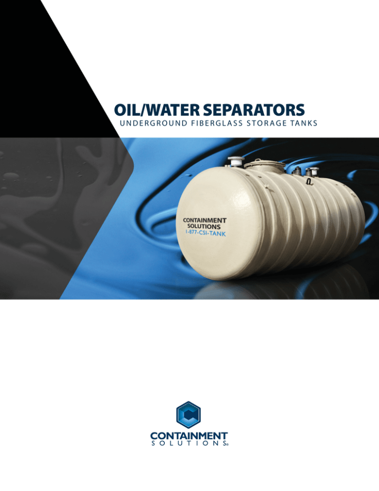
OIL/WATER SEPARATORS
U N D E R G R O U N D F I B E R G L A S S S T O R A G E TA N K S
FIBERGLASS UNDERGROUND OIL/WATER SEPARATORS
Containment Solutions, Inc. (CSI) provides a full range of dependable products for the oil/water separator industry. Our
underground separators utilize the same fiberglass manufacturing technology the petroleum industry relies on for
environmental protection. The inherently non-corrosive properties of fiberglass provide the most compatible option for
your separator application, built by one of the most trusted brands in the world.
CSI separators are constructed to remove hydrocarbons with a specific gravity up to 0.95 through the use of an enhanced
oleophilic coalescer pack system. Oil/water separator designs vary based on required effluent quality and flow rates. An
effluent quality of 10 parts per million (10ppm) is typical but the difference between continuous flow and intermittent flow
will drastically alter the coalescer pack sequence. CSI provides several options in both single and double-wall construction
to meet your unique needs.
For the ultimate in performance, look no further than the CSI UL 2215 separator. The UL 2215 model is a premium oil/water
separator that meets not only construction requirements, but has unparalleled performance testing under both simulated
operating conditions and working conditions. Our UL model takes separators to a new level of effluent quality. The UL
systems are designed for continuous flow, which is a significant distinction when comparing oil/water separator products.
Most products on the market are only engineered for intermittent flow. For intermittent flow applications we offer CSI-10
and CSI-15 models.
SYSTEM PROCESS
CSI fiberglass separators are buried and filled with water. Each separator
includes a combination of baffles and coalescer packs, based on effluent
requirements, to accelerate separation. Waste water enters through
the inlet and gravity naturally settles heavier solids to the bottom of
the tank as the oil floats to the top of the water level. The oily water
then passes through the coalescing plates in a straight flow or cross
flow direction depending on the tank model. The configuration of the
packs efficiently coalesces or joins oil droplets together forming larger
masses of oil that rise to the surface where it accumulates and can be
removed. Gravity displacement discharges the effluent though the outlet at
a lower point in the tank chamber. Separator systems can also be equipped with
electronic monitoring with high oil level alarms, oil stop valve, and control panel.
PERFORMANCE CLAIMS:
• Fiberglass construction provides corrosion resistance without coatings or protection systems.
• Enhanced coalescer system is comprised of oleophilic plates to maximize separation and
minimize maintenance.
• Removable plates simplifies routine cleaning.
• All tanks are built to the stringent performance requirements of UL 1316.
• Removes free floating oils and settleable solids for oil/water mixtures to achieve
10ppm effluent quality (or 15 ppm if specified).
• Includes a 30-year internal / external corrosion and structural warranty.
1 F I B E R G L A S S O I L / WAT E R S E PA R AT O R S
SEPARATOR DESIGN & SIZING
Since each site is unique, the most effective approach is to
analyze each situation and design the system accordingly.
CSI’s engineering staff can help determine the best fit for
your technical considerations and site specific needs.
MODELS
PERFORMANCE
UL 2215
CSI-10
CSI-15
Interceptor
Stokes’ Law
The major design parameters include:
ASTM D-4021
Inlet flow rates
Inlet/outlet concentration
Effluent quality
Specific gravity of contaminants
Oil spill capacity
Oil storage capacity
Temperature
UL 2215 separators are sized primarily on flow rates. A
complete list of flow rate plate pack options are available,
contact your CSI representative for more information.
INTERCEPTORS
In addition to separators, interceptors are available in
single, double, and triple basin designs. CSI interceptors
reduce sand, settleable materials, and oil or grease prior
to sewer discharge. CSI interceptors can be used as stand
alone units or as the initial stage of a more efficient
treatment system utilizing CSI oil/water separators.
UL 1316
API 1630
API 421
USCG 46CFR 162.050
15ppm
10ppm
UL 2215
Continuous Flow
ELECTRONICS / ACCESSORIES
Oil/Water Separator monitoring and control systems can be configured to satisfy a wide range of customer requirements.
Control panels, sensors, probes and gauges are available for double-wall and single-wall oil/water separator systems as
well as for single-tank or multiple-tank installations. CSI carries a full line of pump controls, inlet and outlet pumps, and
waste oil pumps. We can package the right model with the proper electronics so when the tank arrives the only thing left
to do is connect the piping.
APPLICATION: RAINWATER RUNOFF
Oil drippings and spills from parking lots, driveways,
oil terminals and other vehicular traffic surfaces are
being washed into our water supplies by rainwater,
creating serious environmental concerns.
CSI Oil/Water Separators are designed to meet EPA
guidelines for rainwater runoff control.
F I B E R G L A S S O I L / WAT E R S E PA R AT O R S
2
TYPICAL FEATURES
A. Double-Wall Separator
B. FRP Manway Extension
C. Hydrostatic Reservoir
D. Tank Sump
E. Cross flow Baffle
F. Coalescer Plate Packs
G. Oil Stop Valve
H. Anchor Straps
The unique cross flow design of the UL 2215
model results in the most efficient use of the
corrugated plate pack.
I. Deadman Anchor System
TANK DIMENSIONS for CSI-10 & CSI-15 Models
10’ Dia.
8’ Dia.
6’ Dia.
4’ Dia.
Nominal
Capacity
(gallons)
Flow
Rate
(gpm)
Oil
Storage
Capacity
(gallons)
Oil Spill
Capacity
(gallons
Nominal Length
Inlet /
Outlet
(sizes)
Single-Wall
Double-Wall
Nominal Weight (lbs)
Single-Wall
Double-Wall
550
55
110
440
4”
9’ 8”
9’ 9”
425
900
1,000
100
200
800
4”
11’
11’ 1”
500
1,050
1,500
150
300
1,200
4”
16’ 10”
16’ 11”
750
1,275
2,000
200
400
1,600
6”
13’ 10”
13’ 8”
1,000
2,275
3,000
300
600
2,400
6”
16’
16’ 9”
1,075
2,750
4,000
400
800
3,200
6”
19’ 8”
19’ 9”
1,475
2,975
5,000
500
1,000
4,000
8”
24’ 8”
25’
1,800
3,475
6,000
600
1,200
4,800
8”
29’ 6”
30’ 3”
2,100
3,900
6,000
600
1,200
4,800
8”
19’ 5”
19’ 6”
2,300
4,200
7,000
700
1,400
5,600
8”
22’ 2”
23’ 7”
2,650
4,675
8,000
800
1,600
6,400
10”
24’ 11”
26’ 4”
2,950
5,075
9,000
900
1,800
7,200
10”
27’ 8”
27’ 9”
3,300
5,450
10,000
1,000
2,000
8,000
10”
30’ 5”
30’ 6”
3,550
5,950
12,000
1,200
2,400
9,600
10”
35’ 11
36’
4,375
7,000
15,000
1,500
3,000
12,000
12”
44’ 5”
44’ 6”
5,350
8,650
20,000
2,000
4,000
16,000
14”
37’ 8”
37’ 9”
6,950
11,900
25,000
2,500
5,000
20,000
16”
45’ 11”
46’
8,300
13,900
30,000
3,000
6,000
24,000
16’
54’ 2”
54’ 3”
9,600
16,300
40,000
4,000
8,000
32,000
20”
71’ 3”
71’ 4”
12,650
20,975
3 S E PA R AT O R S Y S T E M O V E R V I E W
A
C
D
E
B
G
H
E
F
I
Oleophilic coalescer plate packs are intended to be
removed for cleaning. The number of plate packs will vary
based on tank size and required effluent quality.
S E PA R AT O R S Y S T E M O V E R V I E W
4
FIBERGLASS OIL/WATER SEPARATOR SPECIFICATIONS
Specifications for Oil/Water Separators
(Single-Wall and Double-Wall)
Models CSI-10, CSI-15
Specifications for the UL 2215 model or oil/sand/grit interceptors are available
upon request.
Short Form:
The contractor shall provide fiberglass underground Oil/Water Separators, in
types (single-wall or double-wall) and sizes as shown on the drawings. The
separators shall be manufactured by Containment Solutions.
Separators shall be tested and installed with pea gravel or crushed stone or
approved alternate backfill material, according to the current installation
instructions (Containment Solutions’ Pub. No. OWS 2013 provided with the
tank).
Long Form:
Guide Specification: Containment Solutions’ Fiberglass Underground Oil/
Water Separator.
Part I: General
1.01 Related Word Specified In other Sections
A. Cast-in-place concrete: Section 03300
B. Anchor Bends: Section 05501
C. Plastic Pipe: Section 15064
D. Other related work-such as excavation, concrete or steel piping
1.02 Quality Assurance
A. Acceptable manufacturer - Containment Solutions, Inc. , Conroe, Texas
B. Governing Standards (UL 1316):
1. The API manual on disposal of refinery wastes.
2. API bulletin no. 1630 first edition.
3. API bulletin no. 421.
4. Tank manufactured per ASTM D-4021.
5. Tank must meet National Fire Protection Association (NFPA 30)
Flammable and Combustible Liquids Code.
6. EPA Test Methods 413.1 & 413.2
1.03 Submittals
A. Shop Drawings: Contractor shall submit ______ copies of shop
drawings for each separator. Drawings shall include all critical
dimensions and locations of all fittings and accessories. Material
of construction shall be in accordance with section 1.02 of this
specification.
B. Catalog Data: Contractor shall submit ______ copies of manufacturer’s
literature.
C. Installation Instructions: Contractor shall submit ______ copies of
manufacturer’s installation instructions.
D. Operation and Maintenance Manual: Contractor shall submit
______ copies of manufacturer’s operation and maintenance
manuals.
Part II: Products
2.01 Single-Wall or Double-Wall
Fiberglass Oil/Water Separator
A. Loading conditions - Tank shall meet the following design criteria:
1. External hydrostatic pressure: Buried in ground with 7’ of
overburden over the top of the tank, the hole fully flooded and
safety factor of 5:1 against general buckling. (Contact CSI for
deeper burial depths.)
2. Surface loads: When installed according to manufacturer’s
installation instructions, tanks will withstand surface H-20 axle
loads (32,000 lbs./axle).
3. Internal load: Primary and secondary tanks shall withstand 5 psi
air pressure test with 5:1 safety factor.
4. Tanks shall be designed to support accessory equipment such as
manway extensions, drop tubes, etc. when installed according
to manufacturer’s recommendations and limitations.
B. Product Storage:
1. All primary tanks must be vented. Tanks are designed for
operation at atmospheric pressure only.
5
S P E C I F I C AT I O N S
2. Tanks shall be capable of storing liquids with specific gravities
up to 1.1.
3. Tank shall be capable of storing grease and oils at temperatures
not to exceed 150ºF.
4. Tanks shall be inert to petroleum products.
5. Coalescer plates and associated internal mounting hardware
shall be rustproof.
6. Tanks laminate shall consist of inert material with less than 1%
moisture content.
7. Coalescer plates shall be horizontal, parallel plate design.
8. Coalescers shall be constructed of oleophilic material.
C. Capability and Dimensional Requirements (refer to Containment
Solutions’ literature on gallonage).
1. Nominal volume of the separator shall be _____ gallons.
2. Intermittent flow rate shall be 0 to _____ GPM.
3. Total spill capacity shall be ______ gallons.
4. Inlet oil specific gravity shall range between
_____ and _____ .
5. Effluent discharge quality shall be ______ ppm free oil and
grease.
6. Nominal outside diameter of the separator shall be
_____ feet.
7. Nominal outside diameter of the tank shall be _____ feet.
D. Monitoring Capabilities (Double-Wall Tanks Only):
1. Tanks shall have a space between the primary and secondary
shell walls to allow for the free flow and containment of all
leaked product from the primary tank.
2. The following continuous monitoring conditions shall be
compatible with the cavity between the inner and outer tanks:
• Vented to atmosphere
• Vacuum - 10.2” Hg maximum
• Positive air pressure (3 psi maximum)
• Hydrostatic pressure - 7 foot maximum groundwater head
pressure over tank top.
3. Tanks shall have an integrally mounted reservoir installed on
the tank for optional hydrostatic monitoring. The reservoir shall
be constructed of fiberglass reinforced plastic materials and
warranted for 30 years against failure due to internal/external
corrosion and, when properly installed, against structural failure
(same as tank warranty).
4. Tanks shall be designed with one 4” fitting that will access the
tank bottom between the primary and secondary walls (annular
space).
5. The double-wall tank monitor shall be capable of detecting
a breach in the inner and/or outer tank under the following
installed conditions:
a. When the inner tank is empty.
b. When the inner tank is partially or completely full and the
groundwater table below the tank bottom.
c. When the inner tank is partially or completely full and the
tank is partially or completely submerged in groundwater.
6. The leak detection performance of the monitoring system shall
be tested and verified by a qualified independent consultant to
detect leaks as small as 0.10 gallons per hour from either wall
under all groundwater conditions.
7. All monitoring equipment, including FRP reservoirs and
electronic control, shall be UL-Listed.
8. If hydrostatically monitored, any solution used in the tank
annular space shall have UL approval for compatibility with the
tank and be a contrasting color to the tank surface to facilitate
visual inspection of the tank for leaks prior to burial.
2.02 Accessories
A. Flanged Nozzles
1. Inlet and outlet nozzles shall be of fiberglass or PVC
construction. The nozzles shall have standard 150# ANSI Flange.
2. Nozzles shall be of sufficient size for inlet flow rate.
FIBERGLASS OIL/WATER SEPARATOR SPECIFICATIONS
B.
Fittings Threaded-NPT
1. All threaded fittings shall be located in a manway lid or a tank
mount and be constructed consistently with the requirements
of the UL Label. Fittings to be supplied with threaded cast iron
plugs.
2. All standard threaded fittings to the primary tank and
monitoring cavity are 4” in diameter. all standard threaded
fittings are half-couplings. Reducers are to be used for smaller
sizes where specified and provided by contractor.
3. Thread Standards - All threaded fittings shall have machine
tolerances in accordance with the ANSI standard for each fitting
size.
4. Strength - NPT fittings will withstand a minimum of 150 footpounds of torque and 1,000 foot-pounds of bending, both with
2:1 factor of safety.
5. Location - refer to drawings for location.
6. All rigid internal piping shall be terminated at least 4” from the
bottom of the tank.
C. Flanged Manways:
1. One 29” oval or one 30” round manway will be provided with
each separator. 4’ and 6’ diameter separators greater than 3,000
gallon total capacity will also include on 22” flanged manway. 8’
and 10’ diameter separators greater than 6,000 gallons will also
include one 22” manway.
2. All manways will be furnished complete with UL-Listed gaskets,
bolts and covers.
3. Location - refer to drawing for location.
4. Fiberglass containment collar and turbine enclosure shall be
provided for primary manway. Manway extensions shall be
provided for 22” manways.
D. Secondary Containment Collar - The secondary containment collar
shall be constructed of fiberglass reinforced plastic. Collar shall be
42” or 48” in diameter and will be factory-installed in accordance with
drawings.
E. Optional Oil/Water Separator Monitor & Electronic Accessories
1. Electronic Control Panels - The control panel shall be constructed
of UL-Listed, electronic components. The control panel power
source is 120 volts A.C. (contractor provided wiring). The sensor
monitoring circuit is an intrinsically safe circuit, i.e., the circuit
incapable of releasing sufficient electrical or thermal energy to
cause ignition of specific hazardous material under “normal” or
“fault” operating conditions. The control panel shall be capable
of monitoring single or multiple point oil/water interface sensors
and tank interstitial monitor sensors.
Electrical components rating: Weatherproof (NEMA 4 or 4X)
All control panels shall include:
• Alarm lights for each circuit
• Warning Bell
• Panel housing materials of epoxy coated steel
• Alarm bell silence switch
• Containment Solutions’ electronics do not require shielded
cable
Note: All wiring materials are provided by the contractor. Wiring
is required from the power source to the control panel to the
probe assembly.
2. Oil/Water Interface Sensors
Specifications:
Single or multiple point sensors shall be designed to provide
monitoring of the oil/water interface and to provide accessory
control. Brass models and stainless steel models are available.
3. Reservoir sensor - is detailed in section H2 of the specification.
F.
Optional Anchor Straps - Provide glass fiber-reinforced plastic
anchor straps for each tank shown. Number and location of straps
shall be as specified by manufacturer. Each strap shall be capable of
withstanding the buoyancy load for tank diameter as shown:
4’0
4,200 Lbs.
6’0
- 18,000 Lbs.
8’0
- 25,000 Lbs.
10’0
- 25,000 Lbs.
Straps shall be standard as supplied by the tank manufacturer.
G. Tank Lifting Lugs - Provide lifting lug (s) on all tanks. Lifting lug system
shall be capable of withstanding weight of tanks with a safety factor
of 3:1.
H. Optional Hydrostatic Monitor Accessories
1. Brine Antifreeze
Brine Solution Designation: BAS-30
Chemical Composition: 30%+ calcium chloride, 1% to 3%
Potassium chloride, 1% to 2% sodium chloride, balance water
Visual Appearance: Green in color, odorless fluid
Specific Gravity @ 60ºF: 1.272-1.317
Factory installed on tanks 30,000 gallon and under. Bulk brine
jobsite installed on 35,000 gall and 40,000 gall tanks.
2. Reservoir Sensor - The FHRB 810 reservoir sensor is specifically
designed for installation in the reservoirs of CSI double-wall
tanks. The components of the sensor are compatible with CSI
supplied brine solutions. The sensor is also compatible with
any other control panel that accepts normally open or closed
switches. The sensor provides two alarm points: high brine and
low brine. The sensor can be wired to a control panel to provide
only a single alarm (not distinguishing between high or low
alarms) or it can be wired to report both alarm conditions.
The FHRB 810 reservoir sensor interfaces with Fluid Electronics
control panels. See section 2.02 E1 for additional details.
I. Optional Watertight Turbine Enclosure (Model WTE Series) - The
watertight turbine enclosure consists of fiberglass reinforced plastic
(FRP) enclosure body (variable length in 12” increments, 42” or 48”
ID’s), and FRP reducer (42” x 30” or 48” x 30” ID’s) with o-ring groove
and o-ring gasket, and a push-on FRP lid with two handles. The
reducer opening must be large enough (minimum 28”) to allow for
the removal of a 22” round or 23” x 29” oval manway lid. The lid OD
must be small enough to be removed through a 35” street box. The
enclosure body must be capable of joining to the 42” or 48” diameter
secondary containment collar with a leaktight adhesive joint. The
reducer must be capable of joining to the enclosure body with an
external leaktight adhesive joint to allow for field installation of the
adhesive without enter the enclosure.
With the lid installed, the assembly must provide a water tight seal
with water up to 12” over the lid. The lid includes a non-skid exterior
surface and must be able to support a person standing on the lid
without damage to the lid. One of the lid handles is to be offset to aid
in the removal of the lid and the other is centered on the lid.
Part III: Installation
3.01,3.02 Installation and Testing
Tanks shall be tested and installed according to the current installation
instructions provided with the tank (refer to Containment Solutions’ latest
version of Pub. INST 6001 and OWS 2013)
Specifications for Containment Solutions’ Interceptors
(Single-Wall and Double-Wall)
Short Form:
Provide and install _____ Containment Solutions, Inc. (single basin ((or)),
double basin ((or)), triple basin) interceptor. Interceptor shall be (single-wall
((or)) double-wall Type II) constructed in accordance with UL 1316. Interceptor
shall be ________________ diameter and _____ long. Manufacturer shall
provide written (30) year external and internal corrosion warranty.
While Containment Solutions has taken every precaution as to the accuracy of content and data presented herein, Containment Solutions cannot be held responsible for the individual
interpretation of the data presented, any loss or damage to any property whatsoever, injury or death to any persons whatsoever, or any claims, demands, actions, complaints, proceedings,
judgement, losses, damages, compensation, liabilities, costs or charges, however arising from the unauthorized undirected used of this handbook or the data it contains.
S P E C I F I C AT I O N S
6
CONTAINMENT SOLUTIONS MANUFACTURES:
Underground and Aboveground Storage Tanks
Urea DEF Storage Tanks
Automotive Oil and Lubricant Storage Tanks
Flowtite® Water Tanks
Chemical Storage Tanks
Fiberglass Manholes and Wetwells
5150 Jefferson Chemical Road • Conroe, Texas 77301-6834 • Phone: (936) 756-7731 • www.containmentsolutions.com
Copyright © • Containment Solutions, Inc. • All Rights Reserved • February 2014 • Pub. No. OWS 2001H


