LayerZero Document Number: 94-DA-400650 Rev 1.2
LayerZero Technical Opinion:
On the Inability to Truly Detect Open SCRs on the
Inactive Side of Static Transfer Switches
Background
An open SCR condition on the inactive side of a static
transfer switch cannot be detected. When a switch is in an off
position it is impossible to predict that the switch will conduct
current through it when it is turned on. At best, it may be possible
to ascertain whether the controller that turns the switch on will
operate when it is required to do so.
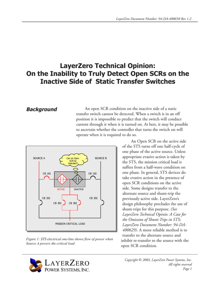
An Open SCR on the active side
of the STS turns off one half-cycle of
one phase of the active source. Unless
appropriate evasive action is taken by
SOURCE A
Can an Open
SOURCE B
SCR be
the STS, the mission critical load is
detected?
suffers from a half-wave condition on
one phase. In general, STS devices do
CB 101
CB 102
take evasive action in the presence of
open SCR conditions on the active
side. Some designs transfer to the
ACTIVE
INACTIVE
alternate source and shunt-trip the
CB 201
CB 202
previously active side. LayerZero’s
CB 301
CB 302
design philosophy precludes the use of
shunt-trips for this purpose. (See
LayerZero Technical Opinio: A Case for
the Omission of Shunt-Trips in STS;
MISSION CRITICAL LOAD
LayerZero Document Number: 94-DA400629). A more reliable method is to
transfer to the alternate source and
Figure 1: STS electrical one-line shows flow of power when
inhibit re-transfer to the source with the
Source A powers the critical load
open SCR condition.
Copyright © 2003, LayerZero Power Systems, Inc.
All rights reserved
Page 1
LayerZero Document Number: 94-DA-400650 Rev 1.2
SCR Operation
for Beginners
SCRs are three-terminal power electronic switches. In the
ON position, current flows from the Anode to the Cathode. In
the OFF position, no current flows from the Anode to the Cathode. The Gate terminal provides the ability to turn the SCR ON.
If sufficient Gate-to-Cathode current is injected in the SCR while
the voltage drop across the Anode-to-Cathode
junction is higher than a prescribed threshold,
then current starts to flow from across the
SCR Fundamentals
Anode-Cathode junction. An SCR conducts
current only in the Anode-to-Cathode direcGate
tion. Current cannot flow in the Cathode-toAnode direction.
Anode
Cathode
In a Static Transfer Switch, each phase
conductor has a pair of SCRs connected in an
anti-parallel arrangement. One side of the antiparallel set of SCRs is connected to a Source
Direction of Current Flow
and the other to the Load. In the Inactive state,
neither of the anti-parallel pair of SCRs is
turned ON. In this state no amount of external
perturbation or experiment can guarantee that
Figure 2: SCR Symbol and Flow of Current
Anode-to-Cathode
current will flow when
called upon at some
Anti-parallel SCR pair
future time. It is entirely
possible that the AnodePositive SCR
to-Cathode junction in
one or both pairs of
SCRs has become
Source
Load
defective and that when
a Gate current is injected to turn the device
ON, there will be no
current flow across the
Negative SCR
Anode-to-Cathode
junction.
• Positive SCR conducts the (+)ve half-cycle of alternating current
The fundamental
• Negative SCR conducts the (-)ve half-cycle of alternating current
assertion in this Technical Opinion is that it is
Figure 3: Anti-parallel SCR pair for AC waveform
Copyright © 2003, LayerZero Power Systems, Inc.
All rights reserved
Page 2
LayerZero Document Number: 94-DA-400650 Rev 1.2
not possible to predict that a switch will close
and conduct current (or will not close and will
not conduct current when required) by observing the switch in its open state. In order to
declare a switch defective, an attempt has to be
made to allow it to carry current.
Open SCR
Gate
Anode
Cathode
An OPEN SCR interrupts AnodeCathode current flow
Figure 4: An Open SCR interrupts current
Current
Conducting SCR Pair
Time
Figure 5: AC
waveform
through an
anti-parallel
SCR pair
Current
Open SCR Condition (Negative SCR)
Time
Figure 6: AC
waveform
through antiparallel SCR
pair with an
Open SCR
condition of
the Negative
SCR
Copyright © 2003, LayerZero Power Systems, Inc.
All rights reserved
Page 3
LayerZero Document Number: 94-DA-400650 Rev 1.2
Open SCR detectors
on Inactive Source
SCR Gate-Cathode Junction Check
Gate
Designers that claim
knowledge about an open SCR
condition on the inactive side
are, in reality, checking the
continuity of the Cathode-Gate
junction. A true check of the
open SCR condition would
involve checking the continuity
of the Anode-Cathode junction. It is entirely possible to
have a healthy Cathode-Gate
junction but an unhealthy
Anode-Cathode junction in an
SCR. In such a case, the open
SCR detectors on the alternate
side of the switch would report
a healthy SCR, whereas in
reality, if the switch were to
transfer to the alternate source,
the SCR would turn out to be
in an Open condition.
Legend:
NEMA Symbol for an
Anti-parallel SCR pair
GateCathode
current
Anode
Cathode
Gate-Cathode continuity is erroneously
flagged as an healthy SCR on the
inactive side
Location of SCR Monitors
SCRs are controlled by driver
circuits called Gate Drives. Open and
shorted SCR detectors often conveniently reside on the Gate Drive
circuit boards. However, if the gate
drive circuit board fails, the system
loses the ability to detect the state of
the SCRs associated with that gate
drive board. If the gate drive board
associated with an Active (i.e. conducting) pair of SCRs fails it results in
the loss of a phase to the load. In
mission critical applications, this is an
unacceptable consequence.
LayerZero’s STS design provides
an SCR monitor that is decoupled
from the Gate Drive circuit boards. If
the Gate Drive circuit board of an
active SCR fails catastrophically
(thereby failing to keep the SCRs
turned ON), the system detects this
condition as an “open SCR” and
transfers the load to the alternate
source. This design feature is embedded in both Triple Modular Redundant and Single Module Redundant
variants of the OPTS product.
Copyright © 2003, LayerZero Power Systems, Inc.
All rights reserved
Page 4


