+ - V - McMaster Physics and Astronomy
advertisement

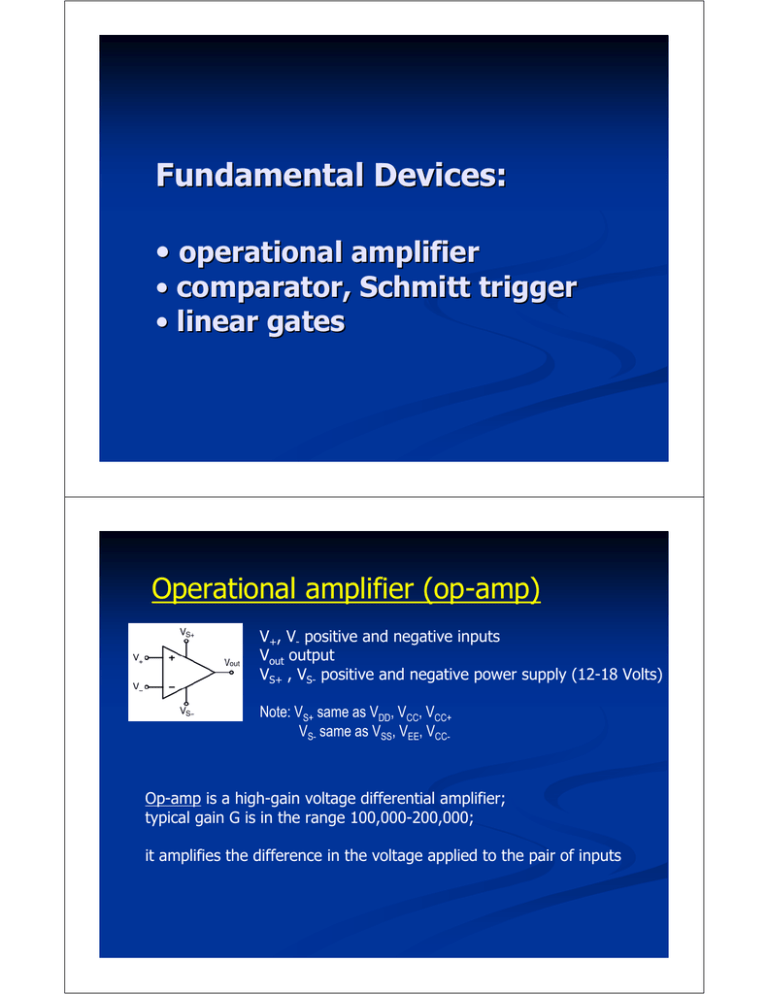
Fundamental Devices: • operational amplifier • comparator, Schmitt trigger • linear gates Operational amplifier (op-amp) V+, V- positive and negative inputs Vout output VS+ , VS- positive and negative power supply (12-18 Volts) Note: VS+ same as VDD, VCC, VCC+ VS- same as VSS, VEE, VCC- Op-amp is a high-gain voltage differential amplifier; typical gain G is in the range 100,000-200,000; it amplifies the difference in the voltage applied to the pair of inputs In typical usage op-amp is controlled by negative feedback, as shown: • can be used as either an ‘inverting’ (negative feedback) or a ‘non-inverting’ (positive feedback) voltage amplifier • no negative feedback, the amplifier is said to be running "open loop" Because the open-loop gain is typically very large, op-amps are not usually used without negative feedback. Unless the differential input voltage is extremely small, open-loop operation results in op-amp saturation =Rf =Ri Inverting op-amp (negative feedback) Vout = − Rf Ri Vin Open loop=no feedback Vout = Vin ⋅ Gopen loop Gopen loop = Vout Vin The ideal op-amp has infinite open-loop gain – this is a model. Real amps only approach this model. Limitations: Finite gain; Finite input resistance Non-zero output resistance Temperature effects To a first approximation, the gain of a typical op-amp is inversely proportional to frequency. Gain & Frequency Gain is fairly uniform at low frequencies, but tends to fall away at high frequencies Historical facts: 1952- K2-W first op-amp, G.A. Philbrick lab 1963- uA702 first solid-state op-amp by Bob Widlar, Fairchild Semiconductors, supply voltages +12 and -6 volts, burn out when temporarily shorted 1965- uA709 by Bob Widlar, high gain, a larger bandwidth, lower input current, supply voltage of approximately +/- 15 Volt DC 1967- LM101 more versatile op-amp version- gain up to 160K and operation range, 'short-circuit' protection, and simplified frequency compensation. In 1968 improved version of LM101 was LM101A, National Semiconductor 1974- RC4558 first multiple op amp device, which uses NPN input transistors, Raytheon Semiconductor's In dated sequence, the op-amp developed like this: 1963-uA702, 1965-uA709, 1967-LM101/LH101, 1968-uA741, 1974-RC4558/LM324, 1975-CA3130/LF355, and in 1976 the TL084... Since 1976 the types of op amps have increased almost daily K2-W op-amps from George A.Philbrick’s lab (1952). Detailed diagram of the common 741 op-amp Absolute Maximum Parameters (741): Typical applications of solid-state integrated circuit operational amplifiers: 1 Linear circuit applications 1.1 Differential amplifier 1.1.1 Amplified difference 1.1.2 Difference amplifier 1.2 Inverting amplifier 1.3 Non-inverting amplifier 1.4 Voltage follower 1.5 Summing amplifier 1.6 Integrator 1.7 Differentiator 1.8 Comparator 1.9 Instrumentation amplifier 1.10 Schmitt trigger 1.11 Inductance gyrator 1.12 Zero level detector 1.13 Negative impedance converter (NIC) 2 Non-linear configurations 2.1 Precision rectifier 2.2 Peak detector 2.3 Logarithmic output 2.4 Exponential output 3 Other applications audio and video pre-amplifiers and buffers differentiators and integrators filters voltage regulator and current regulator analog-to-digital converter digital-to-analog converter The negative feedback connection is the most typical use of an op-amp, but many different configurations are possible, making it one of the most versatile of all electronic building blocks. Non-inverting op-amp Comparator Integrating op-amp Schmitt trigger Comparator Differentiating op-amp Peak detector -is a circuit that compares two analog signals and produces a one bit digital signal -op-amp without feedback V+ V- + - Input voltage not exceed the power voltage The comparator output satisfies the following rules: -when V+ is larger than V- the output bit is 1. -when V+ is smaller than V- the output bit is 0 http://www.facstaff.bucknell.edu/mastascu/eLessonsHTML Comparator- no feedback: Vout = Vs sgn(V+ − V− ) ⎛ −1 , x < 0 ⎞ where sgn x = ⎜ 0 , x = 0 ⎟ ⎜ ⎟ ⎜ 1 , x > 0⎟ ⎝ ⎠ signum function and Vs is the power supply voltage LM-339 a typical comparator chip. internal circuitry LM339 Some applications of comparator: constant fraction discriminator, flash ADC The Schmitt trigger - a comparator with positive feedback Schmitt trigger has some memory- hysteresis. Symbol: The threshold T= R1 Vsat R2 can be adjusted by controlling the resistances R1 and R2. Threshold T changes from − Τ = − R1 R Vsat to Τ = 1 Vsat R2 R2 Vout 1 0 −Τ ∆ Τ The choice of ∆ is important: if ∆ is greater than the amplitude of the noise fluctuations stuttering is eliminated. the effect of using the Schmitt trigger: A B C A – input signal B – comparator response C – trigger response Vin Gates -electronic switch controlled by logical signal. Two basic arrangements: series signal E switch gate 1 closed open 0 open closed shunt signal E switch gate 1 closed closed 0 open open series Open switch exhibit capacitance and closed switch exhibit small resistance. As a result, the high frequency will feed through closed gate. shunt Artifact : control signal may influence the output and hence introduce the distortion (submicrosecond scale). Consider shunt arrangement: •Circuits are designed with balanced gates to minimize the pedestal. •While reducing pedestal short time shifts between balanced gates result in spikes in the output. Some applications 1. Multiplexer In this example, 3-phase time state generator and three linear gates; gates are of series type 2. Event selection Here, gate signal is generated when event “B” occurs. 3. Op-amp with gate selected feedback impedances gates are series type; impedance network works as a filter +


