Installation and Maintenance
advertisement
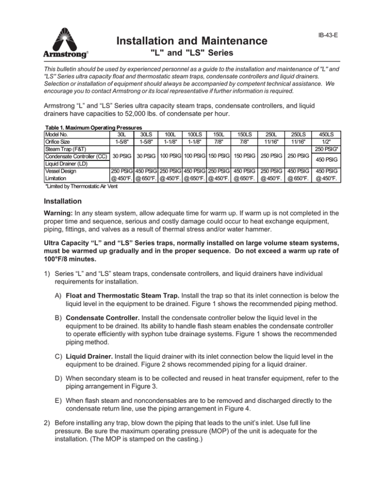
IB-43-E Installation and Maintenance "L" and "LS" Series This bulletin should be used by experienced personnel as a guide to the installation and maintenance of "L" and "LS" Series ultra capacity float and thermostatic steam traps, condensate controllers and liquid drainers. Selection or installation of equipment should always be accompanied by competent technical assistance. We encourage you to contact Armstrong or its local representative if further information is required. Armstrong “L” and “LS” Series ultra capacity steam traps, condensate controllers, and liquid drainers have capacities to 52,000 lbs. of condensate per hour. Table 1. Maximum Operating Pressures Model No. 30L 30LS 100L 100LS 150L 150LS 250L 250LS Orifice Size 1-5/8" 1-5/8" 1-1/8" 1-1/8" 7/8" 7/8" 11/16" 11/16" Steam Trap (F&T) Condensate Controller (CC) 30 PSIG 30 PSIG 100 PSIG 100 PSIG 150 PSIG 150 PSIG 250 PSIG 250 PSIG Liquid Drainer (LD) Vessel Design 250 PSIG 450 PSIG 250 PSIG 450 PSIG 250 PSIG 450 PSIG 250 PSIG 450 PSIG Limitation @ 450°F. @ 650°F. @ 450°F. @ 650°F. @ 450°F. @ 650°F. @ 450°F. @ 650°F. *Limited by Thermostatic Air Vent 450LS 1/2" 250 PSIG* 450 PSIG 450 PSIG @ 450°F. Installation Warning: In any steam system, allow adequate time for warm up. If warm up is not completed in the proper time and sequence, serious and costly damage could occur to heat exchange equipment, piping, fittings, and valves as a result of thermal stress and/or water hammer. Ultra Capacity “L” and “LS” Series traps, normally installed on large volume steam systems, must be warmed up gradually and in the proper sequence. Do not exceed a warm up rate of 100°F/8 minutes. 1) Series “L” and “LS” steam traps, condensate controllers, and liquid drainers have individual requirements for installation. A) Float and Thermostatic Steam Trap. Install the trap so that its inlet connection is below the liquid level in the equipment to be drained. Figure 1 shows the recommended piping method. B) Condensate Controller. Install the condensate controller below the liquid level in the equipment to be drained. Its ability to handle flash steam enables the condensate controller to operate efficiently with syphon tube drainage systems. Figure 1 shows the recommended piping method. C) Liquid Drainer. Install the liquid drainer with its inlet connection below the liquid level in the equipment to be drained. Figure 2 shows recommended piping for a liquid drainer. D) When secondary steam is to be collected and reused in heat transfer equipment, refer to the piping arrangement in Figure 3. E) When flash steam and noncondensables are to be removed and discharged directly to the condensate return line, use the piping arrangement in Figure 4. 2) Before installing any trap, blow down the piping that leads to the unit’s inlet. Use full line pressure. Be sure the maximum operating pressure (MOP) of the unit is adequate for the installation. (The MOP is stamped on the casting.) 3) Set the unit as shown in Figure 1 or 2, with the flange resting on the floor or on a platform for support. Then install and tighten the inlet and discharge piping to secure the unit in its operating position. If the line pressure exceeds 30 psig, install an anchoring bracket as shown in Figure 5 (a) and (b). 4) To allow maintenance and provide maximum service, install a valve on each side of the unit, and a strainer ahead of the inlet. All valves should be of the full-ported type to avoid restricting flow. Note: Use good piping practices. Make inlet piping as short as possible with a minimum of elbows and other restrictions. Install a dirt pocket in the line ahead of the unit as shown in Figures 1 and 2. 5) Liquid Drainers must be back-vented to avoid air binding. DO NOT reduce pipe size for the back vent, but use the full 1-1/2” pipe, connected as shown in Figure 2. Use a full-ported valve in the back-vent line. 6) If the discharge piping is to be elevated, ensure that adequate differential pressure exists at all times to provide proper drainage. Install a check valve in the discharge piping near the unit to prevent backflow when the system is not in operation. 7) Steam Trap and Condensate Controller: If the unit is to be used at near maximum capacity, increase the size of the DISCHARGE piping to a minimum of 3” as near to the outlet fitting as practical. 8) Series “L” and “LS” units do not require priming, They are ready for operation when installed. Maintenance Check the internal mechanism of these units for damage at least once a year. A) Opening the Unit 1) Close the valves in supply, discharge, and vent lines. If the unit is hot, allow it to cool. (Liquid Drainers: close the valve in the back-vent line.) 2) Remove the drain plug from the bottom of the body slowly and allow the liquid to drain. Caution: Do not attempt to remove the body without first removing the thermostatic air vent or fixed orifice and coupling. 3) Before Removing the body: a) Steam Trap: Remove the air vent cap (1-1/2” plug) from the top of the body. When the cap is removed, the thermostatic air vent extends through the top of the body. Using a spanner wrench or needlenose pliers, remove the thermostatic air vent and gasket. Inspect the air vent for indications of damage. The valve should be away from the valve seat. If you have the facilities, place the air vent in a pan of water and heat it to boiling temperature. The valve should close. If the bellows is collapsed or ruptured, or the valve and seat of the vent are eroded, discard it and install a new one. If the unit includes a vacuum breaker, it is located in the air vent cap. Blow through the vacuum breaker from atmosphere side to be sure that it opens; suck air from the same side to be sure that it closes tightly. If the vacuum breaker does not operate properly, discard it and install a new one. 2 b) Condensate Controller: Remove the cap from the body. Remove the fixed orifice air vent and the coupler from the air relief tube. c) Liquid Drainer: Disconnect the back-vent or secondary steam piping from the drainer body. 4) Put blocks under the body of the unit to support it (Weight: 200 lbs. for “L”, 300 lbs. For “LS”) and remove the 12 bolts that attach the body to the cap. To facilitate handling, screw a lifting lug into the 1-1/2” NPT hole in the top of the body. A hoist can be attached to the lifting lug. If an anchoring bracket has been installed behind the flange, remove the anchoring bracket. 5) Carefully pull the body back from the cap, lifting slightly as you pull. Remove and discard the old gasket. 6) Inspect all of the moving parts. Remove all worn or damaged parts and replace them with new parts. Figures 6, 7, and 8 show all critical or moving parts. Check that each item is in good condition and operates normally. Check the float for pinhole leaks, dents or corrosion. Immerse in hot water and look for air bubbles to detect pinhole leaks. 7) If the valve and seat are to be replaced, refer to Section B, “Replacing Valve and Seat.” 8) After inspection and repair, clean the gasket surfaces and place a new gasket between the body and the cap, you may want to use a gasket sealer/cement to hold the gasket on the cap when installing the body. Replace the body carefully to avoid bending the lever, float, or air relief tube (if used). Install and tighten the 12 bolts. (See Figure 9 for bolt tightening sequence.) If the anchoring bracket was removed, reinstall it. 9) Screw the drain plug into the bottom of the body and tighten it securely. 10) a) Steam Trap: Place the thermostatic air vent, with gasket installed, into the coupling at the top of the air relief tube. Tighten with a spanner wrench or pliers. Screw the air vent cap into the top of the body and tighten the cap with a wrench. b) Condensate Controller: Screw the fixed orifice and coupling onto the upper end of the air relief tube. Screw the air vent cap into the top of the body and tighten it with a wrench. c) Liquid Drainer: Reconnect the back-vent piping. 11) Open the valves in the supply and discharge lines. For liquid drainers, also open the valve in the back-vent line. Check the equipment for normal operation. B) Replacing the valve, seat and fulcrum assembly. 1) Refer to Section A, steps 1 through 6 for opening and inspecting the unit. Note: To make quick repairs, remove the two bolts that secure the cap extension, then exchange the cap extension with all attached parts. Use a new gasket. 2) Remove the two fulcrum guide bolts. DO NOT change the adjustment of the lever bolt unless necessary. See Step 5. 3) Lift the float end of the lever and slide the lever, fulcrum, and valve away from the lever bolt. This assembly is then free of the cap extension. 3 4) Use a wrench to remove the old valve seat. 5) Measure the overall thickness of the spacer nut. If the orifice that is to be installed is 1-5/8” diameter, the spacer nut should be 25/32” thick; if any other orifice size is used, the spacer nut should be 5/8” thick. (For the 1-5/8” orifice, the spacer nut should be stamped 1-5/8” or .781) If the correct spacer nut is already installed, do not change the adjustment. If you have to replace the spacer nut, use an anti-seize compound when threading the lever bolt into the cap extension, to prevent galling. 6) Remove the valve-retaining clip by lifting the tab and sliding the clip off. 7) Remove the old valve and install the new one. Replace the fulcrum at the same time. Secure the valve and fulcrum to the lever with a new retaining clip. 8) Install a new valve seat and tighten it securely. The seal is made by metal to metal contact between the ground end of the seat and the flat surface at the bottom of the threaded hole, therefore do not use pipe dope when replacing the valve seat and make sure cap is clean. 9) With the float end of the lever raised, slide the opposite end of the lever under the head of the lever bolt. Lower the float to seat the valve in the valve seat. 10) Check the adjustment of the lever bolt: with the valve seated and the float lever against the bolt head, there should be a 1/32” gap between the fulcrum and the seat (see Figure 10). If this adjustment is incorrect, loosen the spacer nut and adjust the lever bolt accordingly. Retighten the spacer nut. 11) Install the 2 fulcrum guide bolts using an anti-seize compound to prevent galling. 12) If the float was removed, reattach it using a drop of Loktite. 13) Install the trap body and make necessary connections as described in Section A, steps 8-11. Figure 1 Figure 2 "L" and "LS" Steam Trap or Condensate Controller. "L" and "LS" Liquid Drainer *All External Piping by Others 4 Figure 3 Figure 4 Piping arrangement when secondary steam is collected and reused in heat transfer equipment. Piping arrangement when flash steam and noncondensables are to be removed and discharged directly to the condensate. Figure 5 Optional "L" and "LS" Anchoring Bracket Note: Mounting the anchoring bracket behind the flange as in (B) requires that the bracket be completely removed before opening the unit for repair. Figure 6 Figure 7 Figure 9 Steam Trap Condensate Controller Liquid Drainer * All External Piping by Others 5 Figure 8 Figure 8 Bolt Tightening Sequence Cap Extension and Valve Assembly. Armstrong International, Inc. Limited Warranty and Remedy Armstrong International, Inc. (“Armstrong”) warrants to the original user of those products supplied by it and used in the service and in the manner for which they are intended, that such products shall be free from defects in material and workmanship for a period of one (1) year from the date of installation, but not longer than 15 months from the date of shipment from the factory, [unless a Special Warranty Period applies, as listed below]. This warranty does not extend to any product that has been subject to misuse, neglect or alteration after shipment from the Armstrong factory. Except as may be expressly provided in a written agreement between Armstrong and the user, which is signed by both parties, Armstrong DOES NOT MAKE ANY OTHER REPRESENTATIONS OR WARRANTIES, EXPRESS OR IMPLIED, INCLUDING, BUT NOT LIMITED TO, ANY IMPLIED WARRANTY OF MERCHANTABILITY OR ANY IMPLIED WARRANTY OF FITNESS FOR A PARTICULAR PURPOSE. The sole and exclusive remedy with respect to the above limited warranty or with respect to any other claim relating to the products or to defects or any condition or use of the products supplied by Armstrong, however caused, and whether such claim is based upon warranty, contract, negligence, strict liability, or any other basis or theory, is limited to Armstrong’s repair or replacement of the part or product, excluding any labor or any other cost to remove or install said part or product, or at Armstrong’s option, to repayment of the purchase price. As a condition of enforcing any rights or remedies relating to Armstrong products, notice of any warranty or other claim relating to the products must be given in writing to Armstrong: (i) within 30 days of last day of the applicable warranty period, or (ii) within 30 days of the date of the manifestation of the condition or occurrence giving rise to the claim, whichever is earlier. IN NO EVENT SHALL ARMSTRONG BE LIABLE FOR SPECIAL, DIRECT, INDIRECT, INCIDENTAL OR CONSEQUENTIAL DAMAGES, INCLUDING, BUT NOT LIMITED TO, LOSS OF USE OR PROFITS OR INTERRUPTION OF BUSINESS. The Limited Warranty and Remedy terms herein apply notwithstanding any contrary terms in any purchase order or form submitted or issued by any user, purchaser, or third party and all such contrary terms shall be deemed rejected by Armstrong. Special Warranty Periods are as follows: Stainless Steel Products Series 1000, 1800, 2000 — Three (3) years after installation, but not longer than 30 months after shipment from Armstrong’s factory. Armstrong International, Inc., 816 Maple Street, P.O. Box 408, Three Rivers, Michigan 49093 - USA Ph: (616) 273-1415 Fax: (616) 278-6555 IB-43-E 8/01 www.armstrong-intl.com Printed in U.S.A.
