dc-ac inverter unit
advertisement
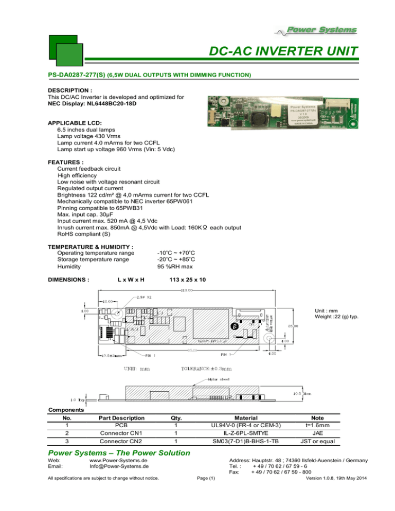
DC-AC INVERTER UNIT PS-DA0287-277(S) (6,5W DUAL OUTPUTS WITH DIMMING FUNCTION) DESCRIPTION : This DC/AC Inverter is developed and optimized for NEC Display: NL6448BC20-18D APPLICABLE LCD: 6.5 inches dual lamps Lamp voltage 430 Vrms Lamp current 4.0 mArms for two CCFL Lamp start up voltage 960 Vrms (Vin: 5 Vdc) FEATURES : Current feedback circuit High efficiency Low noise with voltage resonant circuit Regulated output current Brightness 122 cd/m² @ 4,0 mArms current for two CCFL Mechanically compatible to NEC inverter 65PW061 Pinning compatible to 65PWB31 Max. input cap. 30µF Input current max. 520 mA @ 4,5 Vdc Inrush current max. 850mA @ 4,5Vdc with Load: 160KΩ each output RoHS compliant (S) TEMPERATURE & HUMIDITY : Operating temperature range Storage temperature range Humidity DIMENSIONS : -10°C ~ +70°C -20°C ~ +85°C 95 %RH max LxWxH 113 x 25 x 10 Unit : mm Weight :22 (g) typ. Components No. 1 2 3 Part Description PCB Connector CN1 Connector CN2 Qty. 1 1 1 Material UL94V-0 (FR-4 or CEM-3) IL-Z-6PL-SMTYE SM03(7-D1)B-BHS-1-TB Note t=1.6mm JAE JST or equal Power Systems – The Power Solution Web: Email: www.Power-Systems.de Info@Power-Systems.de All specifications are subject to change without notice. Address: Hauptstr. 48 ; 74360 Ilsfeld-Auenstein / Germany Tel. : + 49 / 70 62 / 67 59 - 6 Fax: + 49 / 70 62 / 67 59 - 800 Page (1) Version 1.0.8, 19th May 2014 DC-AC INVERTER UNIT PS-DA0287-277(S) (6,5W DUAL OUTPUTS WITH DIMMING FUNCTION) Input side CN1: Pin No. CN 1-1+2 CN 1-3+4 CN 1-5 CN 1-6 Symbols GND VIN BRTL BRTH Output side CN2 (SM03(7-D1)B-BHSS-1-TB) Pin No. Symbols Ratings VBLH 430 Vrms (1.88mArms) CN 2-1 VBLH 430 Vrms (1.88mArms) CN 2-2 N. C. CN 2-3 VBLC (GND) CN 2-4 Ratings 4.5~ 5.5 Vdc 0~2.5 Vdc / 0~10 kΏ GND / 0~10 kΏ ELECTRICAL CHARACTERISTICS : Conditions Parameters Symbols Output Current Output Current Input Current Frequency Open Circuit Voltage No Load Shutdown Iout Iout Iin F Vopen Tsd Note 1 : Note 2 : Note 3 : Note 4 : Specification Vin (V) Vbr (V) Tu (°C) Min. Typ. Max. 4,5~5.5 4,5~5.5 4,5~5.5 4,5~5.5 4,5~5.5 4,5~5.5 2.5 0.0 2.5 2.5 2.5 2.5 -10 ~ +70 -10 ~ +70 -10 ~ +70 -10 ~ +70 -10 ~ +70 -10 ~ +70 3.5 1.6 45.5 960 - 4.0 1.8 53.0 1.100 1.0 4.5 2.0 0.52 60.5 1.300 - Unit Note mArms mArms Adc kHz Vrms sec Not e 4 Not e 2 wit hout load Please keep a minimum of 2mm clearance in all directions between inverter high voltage areas and any conductors as marked on mechanical drawing. Dimming range 30% - 100% ≙ 0R ~ 10k; 10k = 100% brightness. Please provide Vcc before applying any control signals into inverter. Revere the sequence during power off which is control signal off first then Vcc. Common current for both CCFL. TEST CIRCUIT : Power Systems – The Power Solution Web: Email: www.Power-Systems.de Info@Power-Systems.de All specifications are subject to change without notice. Address: Hauptstr. 48 ; 74360 Ilsfeld-Auenstein / Germany Tel. : + 49 / 70 62 / 67 59 - 6 Fax: + 49 / 70 62 / 67 59 - 800 Page (2) Version 1.0.8, 19th May 2014

