PART PLAN SECTION B-B SECTION A
advertisement
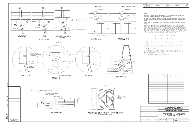
STATE FEDERAL AID SHEET STATE ROUTE C L joint and C L pier C L joint NO. PROJECT VA. D C C ROUTE PROJECT Detail B Detail B " 6 " 6 Section of sealer shown is heavy-duty structural type sealer and may vary slightly depending on manufacturer. As nearly as possible, sides of joints shall be straight, vertical and parallel. The area of the installation shall be free from cracks and spalls. Detail A at abutment Detail D at pier Curb line A typ. Notes: B Sealer shall be installed in one continuous piece except for sidewalk areas. B A Detail D W Detail A W W C Joint width W is the final joint width of the cured concrete when o placed at 60 F. The width W shall be increased or decreased for o every 10 F temperature drop or rise respectively by t. When formed, joint width W shall be reduced by the amount to compensate for the opening of the joint caused by the deflection of the beam when the deck concrete is placed. If the joint is formed so that the form material will not move and the joint will not open as the deck concrete is placed, then adjustment shall not be made. Face of sidewalk curb D C 4d ABUTMENT PIER Face of backwall ABUTMENT OR PIER (SIDEWALK) Fixed Bearing: ’s = L d SECTION A-A PART PLAN Expansion Bearing: SECTION B-B ’s = L d = Total rotation depth from top of slab to point of rotation on bearing. C L joint ’s = Deflection of beam at midspan from dead load of concrete deck slab and bolsters. (See Dead Load Delection Diagram.) L = Length of span. W = Compensation for joint opening due to deflection of beam during placement of concrete deck slab and bolsters for the last span placed adjacent to the joint. Curb line or toe of sidewalk parapet Max. R = " typ. " All the dimensions are in the same units. 1" 11" 11" Curb line 1 Lubricant adhesive R = 10" 8" R C L joint 1’ -1" R = 9" C L joint " " 4" R 2" Face of backwall Preformed sealer Preformed sealer DETAIL A DETAIL D Abutment SECTION C-C Pier Sealer Size b Sealer Depth h Joint Width W t bej2. dgn DETAIL B b Face of sidewalk curb 2’-0" 06-14-2010 Cut and miter sealer. Field vulcanize. Do not cut above this line " 1" 1" h/2 m ax. " typ. h See Detail B COMMONWEALTH OF VIRGINIA DEPARTMENT OF TRANSPORTATION Preformed sealer STRUCTURE AND BRIDGE DIVISION BEJ-2 SECTION D-D PREFORMED ELASTOMERIC JOINT SEALER PREFORMED ELASTOMERIC JOINT DETAILS In uncompressed state No. VDOT S&B DIVISION RICHMOND, VA STRUCTURAL ENGINEER Not to scale c 2010, Commonwealth of Virginia Description Revisions Date Designed: ........... S&B DIV Drawn: ................ Checked: ............ Date Plan No. BEJ-2 Sheet No. PREFORMED ELASTOMERIC JOINT DETAILS SKEWED CROSSING OVER 20°° NOTES TO DESIGNER: See Part 2, Chapter 14 of this manual to determine size of joint required. Standard to be used for skews > 20°. ADD THE FOLLOWING NOTES, DIMENSIONS, DETAILS, ETC. TO STANDARD: Complete table entering as appropriate either abutment or pier designation, sealer size (b), sealer depth (h), joint width (w) and temperature variation per 10°F± (t). Section D-D: Modify details as needed for rail type used. PART 3 STANDARD BEJ-2: NOTES TO DESIGNER DATE: 18May2016 SHEET 2 of 2 FILE NO. BEJ-2-2
