EVQ8632-LE-8-00A
High Efficiency, 8A,18V
Synchronous Step-Down Converter
Evaluation Board
DESCRIPTION
FEATURES
The EVQ8632-LE-8-00A is an evaluation board
for the MPQ8632GLE-8, a high efficiency
monolithic synchronous step-down converter.
The EV board can deliver 8A continuous load
current over a wide 8V to 18V operating input
range. High efficiency can be achieved over a
wide output current load range.
Constant-On-Time
(COT)
control
mode
provides fast transient response and eases loop
stabilization.
Wide 8V to 18V Operating Input Range
8A Output Current
Low RDS(ON) Internal Power MOSFETs
Proprietary Switching Loss Reduction
Technique
Adaptive COT for Ultrafast Transient
Response
Programmable Soft Start Time
Pre-Bias Start up
Programmable Switching Frequency from
200kHz to 1MHz
Non-latch OCP, OVP Protection and
Thermal Shutdown
Output Adjustable from 0.611V to 13V
Available in a QFN3x4 Package
This EV board can be turned on or shut down via
a remote ON/OFF input that is referenced to
ground. This input is compatible with popular logic
devices.
ELECTRICAL SPECIFICATION
APPLICATIONS
Parameter
Symbol
Value
Units
Input Voltage
Output Voltage
VIN
VOUT
8 – 18
1.8
V
V
Output Current
IOUT
8
A
Telecom System and Base Stations
Networking Systems and Server
Personal Video Recorders
Flat Panel Television and Monitors
Distributed Power Systems
All MPS parts are lead-free and adhere to the RoHS directive. For MPS green
status, please visit MPS website under Products, Quality Assurance page.
“MPS” and “The Future of Analog IC Technology” are registered trademarks of
Monolithic Power Systems, Inc.
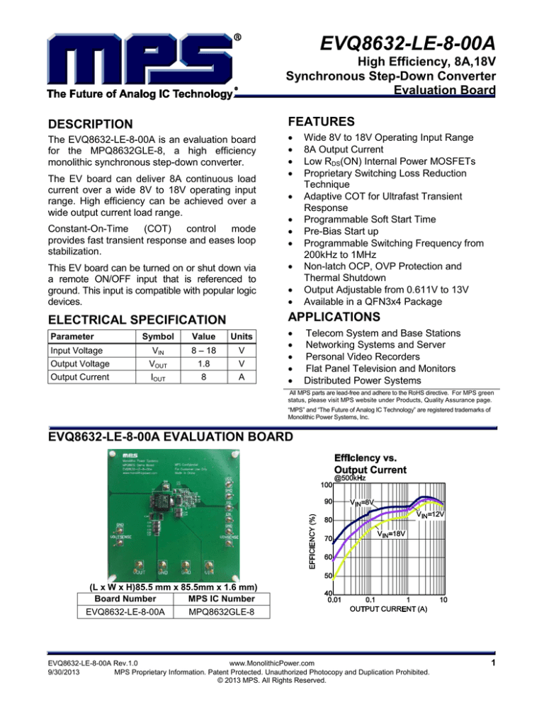
EVQ8632-LE-8-00A EVALUATION BOARD
(L x W x H)85.5 mm x 85.5mm x 1.6 mm)
Board Number
MPS IC Number
EVQ8632-LE-8-00A
MPQ8632GLE-8
EVQ8632-LE-8-00A Rev.1.0
www.MonolithicPower.com
9/30/2013
MPS Proprietary Information. Patent Protected. Unauthorized Photocopy and Duplication Prohibited.
© 2013 MPS. All Rights Reserved.
1
EVQ8632-LE-8-00A – HIGH EFFICIENCY, 8A, 18V, SYNCHRONOUS STEP-DOWN CONVERTER
EVALUATION BOARD SCHEMATIC
EVQ8632-LE-8-00A Rev.1.0
www.MonolithicPower.com
9/30/2013
MPS Proprietary Information. Patent Protected. Unauthorized Photocopy and Duplication Prohibited.
© 2013 MPS. All Rights Reserved.
2
EVQ8632-LE-8-00A – HIGH EFFICIENCY, 8A, 18V, SYNCHRONOUS STEP-DOWN CONVERTER
EVQ8632-LE-8-00A BILL OF MATERIALS
Qty
Ref
Value
2
C1A, C1B
10μF
4
C1C, C1D,
C2E,C3
0.1μF
1
C1E
NS
1
C2A
C2B, C2C,
C2D
NS
3
47μF
Description
Ceramic Capacitor;
35V;X7R;1210;
Ceramic Capacitor;
50V;X7R;0603
Ceramic Capacitor;
35V;X7R;1210;
C4
82pF
1
C5
1μF
1
C6
220nF
3
C7, C8, C2F
EN, GND2,
GND_1,
GND_3, PG,
SW, VCC,
VINSENSE,
VOUTSENSE
GND, GND1,
VIN,VOUT,
NS
1
L1
1.2μH
1
1
1
1
2
R1
R2
R3
R4
R8, R6
20k
10k
4.7
2M
100k
1
R7
634k
Inductor;1.2μH;2m
Ohm;25A
Film Resistor;1%
Film Resistor;1%;
Film Resistor;5%
Film Resistor;5%;
Film Resistor;1%;
Film Resistor;1%
1
R5
499k
1
R9
2k
1
U1
4
Manufacturer
Part Number
1210
muRata
GRM32ER7YA106KA12L
0603
muRata
GRM188R71H104KA93D
1210
POSCAP
Ceramic Capacitor;
6.3V;X5R;1206
Ceramic Capacitor;
50V;COG;0603
Capacitor;25V;X7R
Ceramic Capacitor;
25V;X7R;0603
1
9
Package
1206
TDK
C3216X5R0J476M
0603
muRata
GRM1885C1H820JA01D
0603
muRata
GRM188R71E105KA12
0603
muRata
GRM188R71E224KA88
0603
Connector
CONN/1MM
Connector
CONN/2MM
SMD
Wurth
744325120
0603
0603
0603
0603
0603
Yageo
Yageo
Yageo
Yageo
Yageo
0603
Yageo
RC0603FR-0720KL
RC0603FR-0710KL
RC0603JR-074R7L
RC0603JR-072ML
RC0603FR-07100KL
RC0603FR-07634KL
Film Resistor;1%
0603
Yageo
RC0603FR-07499KL
Film Resistor;1%;
Step
Down
Converter
0603
Yageo
RC0603FR-072KL
QFN 3X4
MPS
MPQ8632GLE-8
EVQ8632-LE-8-00A Rev.1.0
www.MonolithicPower.com
9/30/2013
MPS Proprietary Information. Patent Protected. Unauthorized Photocopy and Duplication Prohibited.
© 2013 MPS. All Rights Reserved.
3
EVQ8632-LE-8-00A – HIGH EFFICIENCY, 8A, 18V, SYNCHRONOUS STEP-DOWN CONVERTER
EVB TEST RESULTS
Performance waveforms are tested on the EVQ8632-LE-8-00A evaluation board.
VIN = 12V, VOUT = 1.8V, L = 1.2µH, TA = +25ºC, unless otherwise noted.
EVQ8632-LE-8-00A Rev.1.0
www.MonolithicPower.com
9/30/2013
MPS Proprietary Information. Patent Protected. Unauthorized Photocopy and Duplication Prohibited.
© 2013 MPS. All Rights Reserved.
4
EVQ8632-LE-8-00A – HIGH EFFICIENCY, 8A, 18V, SYNCHRONOUS STEP-DOWN CONVERTER
EVB TEST RESULTS (continued)
Performance waveforms are tested on the EVQ8632-LE-8-00A evaluation board.
VIN = 12V, VOUT = 1.8V, L = 1.2µH, TA = +25ºC, unless otherwise noted.
EVQ8632-LE-8-00A Rev.1.0
www.MonolithicPower.com
9/30/2013
MPS Proprietary Information. Patent Protected. Unauthorized Photocopy and Duplication Prohibited.
© 2013 MPS. All Rights Reserved.
5
EVQ8632-LE-8-00A – HIGH EFFICIENCY, 8A, 18V, SYNCHRONOUS STEP-DOWN CONVERTER
EVB TEST RESULTS (continued)
Performance waveforms are tested on the EVQ8632-LE-8-00A evaluation board.
VIN = 12V, VOUT = 1.8V, L = 1.2µH, TA = +25ºC, unless otherwise noted.
EVQ8632-LE-8-00A Rev.1.0
www.MonolithicPower.com
9/30/2013
MPS Proprietary Information. Patent Protected. Unauthorized Photocopy and Duplication Prohibited.
© 2013 MPS. All Rights Reserved.
6
EVQ8632-LE-8-00A – HIGH EFFICIENCY, 8A, 18V, SYNCHRONOUS STEP-DOWN CONVERTER
PRINTED CIRCUIT BOARD LAYOUT
Figure 1—Top Silk Layer
Figure 3—Inner Layer 1
Figure 2—Top Layer
Figure 4— Inner Layer 2
Figure 5—Bottom Layer
EVQ8632-LE-8-00A Rev.1.0
www.MonolithicPower.com
9/30/2013
MPS Proprietary Information. Patent Protected. Unauthorized Photocopy and Duplication Prohibited.
© 2013 MPS. All Rights Reserved.
7
EVQ8632-LE-8-00A – HIGH EFFICIENCY, 8A, 18V, SYNCHRONOUS STEP-DOWN CONVERTER
QUICK START GUIDE
1. Connect the positive and negative terminals of the load to the VOUT and GND pins,
respectively.
2. Preset the power supply output between 8V and 18V, and then turn off the power supply.
3. Connect the positive and negative terminals of the power supply output to the VIN and GND
pins, respectively.
4. Turn the power supply on. The MPQ8632GL will automatically startup.
5. To use the Enable function, apply a digital input to the EN pin. Drive EN higher than 2V to turn
on the regulator or less than 0.4V to turn it off.
6. Use R1 and R2 to set the output voltage with VFB = 0.611 V. Follow the Application Information
section in the device datasheet to select the proper value of R1, R2, inductor and output
capacitor values when output voltage is changed.
7. If lower ripple at light loads is needed, then use a larger L1. But with the larger L1, the transient
response peak to peak value will become larger too.
NOTICE: The information in this document is subject to change without notice. Please contact MPS for current specifications.
Users should warrant and guarantee that third party Intellectual Property rights are not infringed upon when integrating MPS
products into any application. MPS will not assume any legal responsibility for any said applications.
EVQ8632-LE-8-00A Rev.1.0
www.MonolithicPower.com
9/30/2013
MPS Proprietary Information. Patent Protected. Unauthorized Photocopy and Duplication Prohibited.
© 2013 MPS. All Rights Reserved.
8


