Instructionj Leaflet IL04210004E
Effective July 2010
Supersedes April 2010
ZEB-XRR-24
ZEB-XRR-120
Electronic Remote Reset Module
Product Installation
Table 1. Modbus Settings
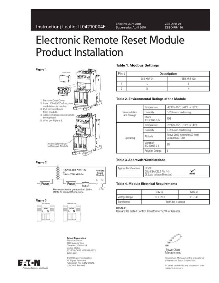
Figure 1.
Dust Cover.
Pin #
Description
ZEB-XRR-24
1
L
L
2
N
N
Table 2. Environmental Ratings of the Module
1. Remove Dust Cover.
2. Insert C440-XCOM module
until detent is reached.
3. Pull terminal block
from module.
4. Assure module was retained
by overload.
5. Wire per Figure 2.
Transportation
and Storage
Operating
Insert Screwdriver
to Remove Module
120Vac ZEB-XRR-120
or
24Vac ZEB-XRR-24
Fuse
Remote
Reset
Module
L
RESET
Agency Certifications
Figure 3.
24 VAC
N
Humidity
5-95% non-condensing
Shock
IEC 60068-2-27
15G
Temperature
-25°C to 65°C (-13°F to 149°F)
Humidity
5-95% non-condensing
Altitude
Above 2000 meters (6600 feet)
Consult FACTORY
Vibration
IEC-60068-2-6
3G
Polution Degree
3
ZEB-XRR-120
120 VAC
L
N
UL508
CUL (CSA C22.2 No. 14)
CE (Low Voltage Directive)
RoHS
Table 4. Module Electrical Requirements
Voltage Range
L
-40°C to 85°C (-40°F to 185°F)
N
For reset circuits greater than 305m
(1000 ft) consult the factory.
ZEB-XRR-24
Temperature
Table 3. Approvals/Certifications
Figure 2.
Fuse
ZEB-XRR-120
Transformer
24V ac
120V ac
19.2 -28.8
96 - 148
50VA for 1 second
Notes:
Use any UL Listed Control Transformer 50VA or Greater.
Eaton Corporation
Electrical Sector
1111 Superior Ave.
Cleveland, OH 44114
United States
877-ETN-CARE (877-386-2273)
Eaton.com
© 2010 Eaton Corporation
All Rights Reserved
Publication No. IL04210004E
July 2010, Rev 002
PowerChain Management is a registered
trademark of Eaton Corporation.
All other trademarks are property of their
respective owners.


