Nov 2015
Improving Cable Quality & Reliability
Resistance Measurement to
within 1mΩ
A How-To Guide: Precision resistance measurements of less than
0.1Ω reveal wiring defects not visible to less sensitive measurements,
Use this measurement technique to improve cable quality & reliability.
42 Nagog Park, Suite 115, Acton, MA 01720
(978) 266 2655
camiresearch.com
Improving Cable Quality & Reliability:
Resistance Measurement to within 1mΩ
Small Faults, Big Problems
Four-Wire Kelvin measurement makes it
possible to accurately measure resistance
values less than 0.1 Ω while eliminating the
inherent resistance of the lead wires connecting
the measurement instrument to the component
being measured. A high-quality Digital
Multimeter (DMM) test lead of 24” in length with
banana plugs at both ends will typically present
a natural resistance of about 0.1 Ω. When using
two such leads connected to the Unit Under
Test (UUT), we can expect at least 0.2 Ω of the
measured value to be contributed by the meter
leads alone. In addition, the slightest bit of
contamination on the banana plug leads,
whether from finger oils, dust, or corrosion, will
add additional resistance or cause the
measured value to appear variable when the
lead wires or plugs are flexed.
Precision low-value resistance measurements
become necessary when testing cables intended to carry significant current, or when
extremely high reliability must be ensured in
medical or military applications. For cables
intended to transmit power as you might find in
AC power distribution or radio transmitters, lowresistance connections that have faulted to
high-resistance create the real danger of fire or
explosion. Although cables used in medical
applications, for example, do not carry
significant current, questionable connections to
hair-thin wires connecting a monitor to highprecision sensors could create life-critical
measurement error or result in circuit
misoperation. Milliohm-sensitive 4-wire
measurement helps to locate bad solder joints,
faulty crimps, recessed pins, pin contact
contamination, improper wire gauge, and
stress-extruded wire – errors that could go
undetected with by other methods. For
integration with other test equipment, PC-based
systems often include API and LabView
interfaces.
Additionally, being independent of embedded
computer architecture, PC-based tester
hardware is more robust, easier to upgrade, and
has a longer lifecycle. Consistent with mixedmodel manufacturing requirements, companies
that require a flexible versatile test system, with
dynamic graphic-rich GUI, archival datalogging, and ISO9000 quality documentation
typically benefit from PC-based systems.
“Many unfortunate accidents have
developed in the past because of
high-resistance connections in
cables and wire harnesses which,
in some cases, resulted in loss of
life. This underscores the
importance of accurately measuring
resistance at the time these
electrical components are
manufactured, and in the cases of
wiring assemblies continuously in
motion, as in aircraft, through
periodic inspections.”
-Christopher Strangio,
CAMI Research Inc.
camiresearch.com
© 2016 by CAMI Research Inc.
All Rights Reserved
2
Improving Cable Quality & Reliability:
Resistance Measurement to within 1mΩ
What is 4-Wire Measurement?
Ohm’s law defines resistance, “R”, as the ratio
of voltage “V” across a component, to the
current “I” passing through it:
R = V/I
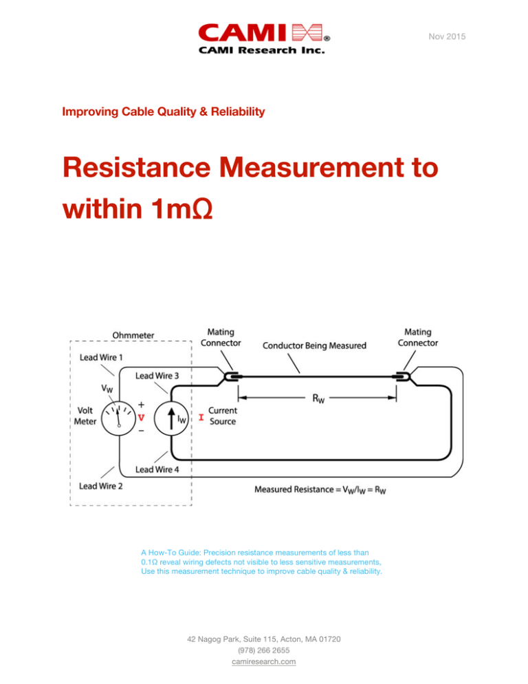
To measure resistance, we apply a test current
to a wire and detect the voltage drop
developed. From this, we easily calculate the
resistance as shown in Fig. 1.
Figure 1: Two-wire resistance measurement.
We measure the resistance of interest, RW,
between the conductor’s two mating pins. The
entire circuit, however, includes the resistance of
the lead wires, RL1 and RL2, so the voltage drop
used in the calculation includes all three of these
resistances. In many situations the lead wire
resistance is much lower than the resistance of
the conductor or component we aim to measure
and therefore can be disregarded.
In some situations, however, the resistance of
interest, RW, approaches the resistance value of
the lead wires used to measure it resulting in an
inaccurate reading. We correct this problem by
moving the voltage measurement points out to
the endpoints of the mating pins, thus, bypassing
any voltage drop that may occur in the lead wires
(Fig. 2).
camiresearch.com
© 2016 by CAMI Research Inc.
All Rights Reserved
3
Improving Cable Quality & Reliability:
Resistance Measurement to within 1mΩ
Figure 2: Four-wire resistance measurement.
The Ohmmeter then appears to have four wires
coming from it. The image below (Fig. 3) shows
these terminals on a typical DMM.
Because we now use four lead
wires instead of two, we refer to
this approach as “4-wire
measurement”, or alternatively “4Wire Kelvin” measurement in
honor of the 19th century British
physicist, Lord Kelvin, who
originally developed it.
voltage drop across it regardless of its length.
This important point means that lead wires may
now be quite long, sometimes
exceeding 10 feet (3 meters),
without having any effect on the
measurement. Long lead wires
become necessary when testing
large, multi-branch wire harness
assemblies, so this situation is
not as uncommon as it might
seem.
Note that the current flowing
The principal advantage of 4-wire
through the voltage-measuring
measurement is that it eliminates
circuit of a 4-wire system is
any effect of fixture resistance
extremely small, typically on the
(the lead wires) to obtain a
order of fractions of a microamp
precise
resistance value of the
Figure 3: Lead inputs for 4-wire
(six or more orders of magnitude
UUT. Because 4-wire
measurement.
less than the source current), so
measurements typically employ
virtually no voltage drop occurs across these lead
test currents well above those needed for twowires, and its effect on the resistance
wire testing, a secondary advantage comes
measurement is negligible. In summary, if there is
through the use of a high-current stress test for
no current flowing through a wire, there is no
camiresearch.com
© 2016 by CAMI Research Inc.
All Rights Reserved
4
Improving Cable Quality & Reliability:
Resistance Measurement to within 1mΩ
wiring by driving a current of 1 A or more through
each conductor, and the ability to set a dwell time
from 100 ms to many minutes –– observing a
slowly-increasing resistance during a long dwell
period resulting from thermal heating may reveal
problems not detected with a shorter
measurement interval.
modern cable test equipment offers a multitude
of programmable test connections, also referred
to at test points, to which the UUT may be
connected. Typical cable testers start with
128 test points and can be expanded upward
into the thousands of points.
Software driving a 4-wire measurement system
should permit individual conductors within a UUT
to be independently disabled from a 4-wire test
by User selection to avoid potential damage to
fuses or other component not intended to carry
high test current. Users should also be allowed to
independently set different test currents and dwell
times for different conductors.
The advantages of 4-wire measurement come at a
cost. First, the test system requires twice the
number of test points that would normally be
required for two-wire resistance measurement
significantly increasing the equipment cost.
Second, test fixtures must utilize two wires for
every pin on the mating connector, one wire for
the current source, and the other for voltage
sense. This increases the cost and complexity of
the test fixture.
Building Test Fixtures for 4-Wire
Measurement
An example 4-wire test fixture intended for a 12conductor cable appears in the image below. If we
assume that the UUT is a cable with two
connectors, an identical fixture would be needed
for both connectors.
Unlike a benchtop DMM which has four test
connections (two for Source and two for Sense),
Figure 4: Example 4-wire test fixture for a 12-conductor cable.
camiresearch.com
© 2016 by CAMI Research Inc.
All Rights Reserved
5
Improving Cable Quality & Reliability:
Resistance Measurement to within 1mΩ
The UUT attached to a CableEye® test system
appears in Fig. 5. You can see that 48 test points
are required to test this 12-conductor cable.
When building 4-wire test fixtures, we typically
assign odd numbered test points for the Source
and even number pins for the Sense. This may
also be reversed, if that is your standard.
However, once you agree on a standard, all
fixtures should be wired in this manner. Keep in
mind the following additional considerations:
1. Because the Source pin can drive a
current of 1 A or more into a pin, we
recommend using 22-gauge or larger
wire for this purpose. The Sense pin,
however, will carry almost no current at
all, so the wire used for Sense can be a
much thinner which might be an
advantage when trying to crimp two wires
into a single pin of the mating connector.
Figure 5: Connected 4-wire test fixture.
Typical high-performance cable test equipment
like the CableEye system not only provide 4-wire
measurement, but also high voltage testing to
check for dielectric breakdown and insulation
resistance. With the cost of this equipment
ranging from $25 to $50 per- test-point
depending on the total number of points ordered,
the equipment cost can be significant, especially
for larger assemblies.
Construction of the test fixture itself contributes
to the overall cost of testing because of the
number of wires employed, and the requirement
that Source and Sense leads be joined at each
pin in the mating connector. When high-density
mating connectors must be used, there may not
be sufficient space within the backshell of the
mating piece to accommodate two wires if the
connector was designed for one, and this then
entails splicing a short single extension wire from
each mating pin to the wire pair, soldering the
three pieces together, and insulating with heatshrink tubing. Because test fixtures are not massproduced but, instead, custom designed and
hand-assembled, a typical test fixture for 4-wire
harness testing may cost from many hundreds to
thousands of dollars.
2. The length of the wire in the test fixture is
unimportant in 4-wire measurements
since the lead wire is not part of the
resistance measurement. 4-Wire
methodology may be especially
advantageous when the UUT is
‘remotely’ located. Consider, for example,
a UUT placed in an environmental
chamber some distance away from the
test equipment. Test leads of
considerable length can be fed through a
sealed access port into the chamber to
obtain precision measurement remotely.
The total effective fixture length is long,
yet its resistance is not part of the
measurement. Note that for very long
Source wires with resistance exceeding
about 5 Ω, we must ensure that the
voltage of the 4-wire system can rise
sufficiently to drive the specified current
through this wire.
3. Before building the fixture, be sure that
your test equipment has sufficient test
points for the fixture you need: TWO test
points for every pin in your mating
connectors. To determine the minimum
test point requirement, add up all the pins
camiresearch.com
© 2016 by CAMI Research Inc.
All Rights Reserved
6
Improving Cable Quality & Reliability:
Resistance Measurement to within 1mΩ
on all the connectors of your cable or
harness, including any ground or shell
conductors, and double this number to
determine the total required test points.
ensure that an odd-numbered test point ‘n’ and
the even-numbered test point immediately next in
the sequence ‘n+1’ attach to the same pin on the
mating connector.
4. Several testers presently on the market
use 64-pin dual-row latch headers as
seen below (Fig. 6). For this type of test
point interface, we recommend using
Ampmodu connectors or their equivalent
which consist of a 64-pin socket body
and gold-plated crimp-and-poke pins.
These connectors offer superior lowresistance connections to the header,
high voltage isolation exceeding
1500 Vdc, and rugged construction.
Figure 6: 64-Pin Latch Header (top) and Ampmodu
Socket (bottom)
When building fixtures for multi-headed cables or
wire harnesses with this type of connector, you
may wire multiple connectors to a single
Ampmodu connector to avoid wasting test
valuable points. When you do this, always
Figure 7: Multiple mating connectors into a single
Ampmodu (Top). Single mating connector into multiple
Ampmodus (Bottom)
camiresearch.com
© 2016 by CAMI Research Inc.
All Rights Reserved
7
Improving Cable Quality & Reliability:
Resistance Measurement to within 1mΩ
Here (Fig. 10) you see the screen report from the
CableEye tester with all but two strands cut.
What Difference Does One
Strand Make?
This demonstration of 4-wire measurement
sensitivity begins with a 3.5” (8.9 cm) length
of 22-gauge 7-strand wire, UL07730 connected
between two screw terminals. The UUT runs
between Source test points 49 and 55, with
corresponding Sense test points 50 and 56
appropriately linked, as shown in the next photo
(Fig. 8).
Figure 10: CableEye screen report of 4-wire test.
Table 1 summarizes how the resistance changes
as strands are cut, and as a function of dwell
time. Interestingly, with only one strand remaining
to carry the 1 A test current, no heating was
detectable by human touch, although clearly the
resistance increased slightly with the current
applied for 1 second or longer compared to the
initial short 50 ms dwell.
Figure 8: Experimental set-up with 7 intact strands of
22-gauge wire.
The strands will be cut, one-by-one, with resistor
measurements made at each step, to determine
how the resistance varies with the number of
intact strands. This photo (Fig. 9) shows three cut
strands with four strands remaining.
Table 1: Experimental results - Change in resistance
as strand are cut.
Similarly simple commands can be added to wait
for a variety of signals (barcode, speech, remote
etc.) from the operator, and output any number of
responses (lights, latches, tones, labels etc.).
Figure 9: Experimental set-up with 4 intact strands of
7 strand, 22-gauge wire.
camiresearch.com
© 2016 by CAMI Research Inc.
All Rights Reserved
8
Improving Cable Quality & Reliability:
Resistance Measurement to within 1mΩ
Conclusion
Application of 4-wire Kelvin measurement
techniques will improve the quality and
reliability of your cable and harness products.
Precision resistance measurements of less than
0.1 Ω reveal wiring defects not visible to less
sensitive measurements, including bad solder
joints, faulty crimps, recessed pins, pin contact
contamination, improper wire gauge, and
stress-extruded wire. Resistive losses resulting
from these defects in applications carrying
current above 1 A may cause excessive heat
generation or fire in wiring, or in the case of
measurement circuits which obtain input from
precision sensors, may cause false reporting or
circuit misoperation. The 4-wire Kelvin
resistance method not only makes it possible
to obtain milliohm- or microohm-sensitive
measurements, but eliminates any effect of
incidental resistance that would be introduced
by test leads or the test fixture. Achieving these
benefits, however, requires test equipment with
twice the number of test points than would
otherwise be necessary, and a test fixture with
two wires leading from the tester to every pin
on the mating connector.
camiresearch.com
© 2016 by CAMI Research Inc.
All Rights Reserved
9
Improving Cable Quality & Reliability:
Resistance Measurement to within 1mΩ
CableEye®
CableEye is an expandable and upgradable diagnostic
and Pass/Fail Cable and Harness Test System that’s PCbased. It’s used for assembly, prototyping, production,
and QC of standard or custom wire cables and
harnesses, and comes in six models:
Low Voltage: M2U-basic, M2U
For diagnostic and Pass/Fail Testing - Find,
display, log, & document: continuity (opens,
shorts, miswires), and intermittent connections
Barcode scanning & automated label printing
Low Voltage: M3U, M3UH
For all of the above plus resistance (contact,
isolation, embedded), and diodes (orientation,
forward voltage, reverse breakdown).
Low Voltage and High Voltage: HVX, HVX-21
For all of the above plus 4-wire & HiPot (dielectric
withstand voltage, and insulation resistance).
Free 2-Week Trial
Experience CableEye first-hand. See how your own
cables and connectors can be auto-detected and
accurately represented on our graphic-rich, touch
screen compliant GUI. Find cable problems fast, and
understand why customers tell us "... we cannot live
without CableEye" (Kabelservice), declaring it the "...
best, easiest to use, system" (Digital Video Products).
Automatic report generation
Testimonials
Limited Availability w No Credit Card Required
No Commitment to Purchase
Learn why companies choose CableEye Cable &
Book Trial Now!
Harness Testers. Scan this code to read our
testimonials.
(978) 266 2655
camiresearch.com/get-demo.html
camiresearch.com
© 2016 by CAMI Research Inc.
All Rights Reserved
10


