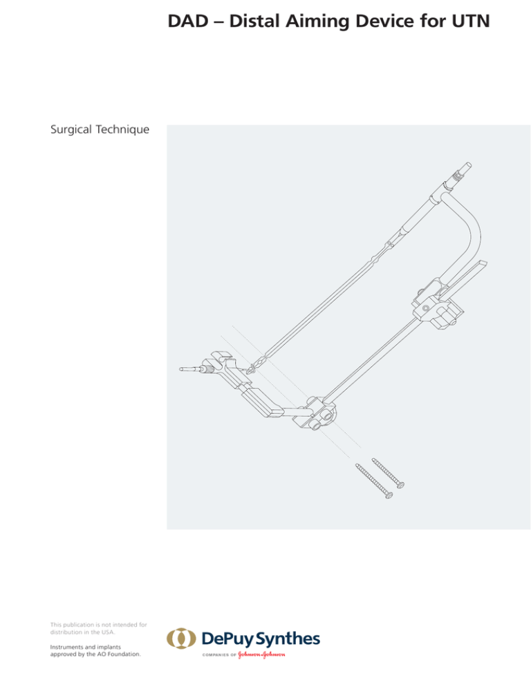
DAD – Distal Aiming Device for UTN
ht
e
ic
rs
üb
em
st
Sy
Surgical Technique
This publication is not intended for
distribution in the USA.
Instruments and implants
approved by the AO Foundation.
Image intensifier control
This description alone does not provide sufficient background for direct use
of DePuy Synthes products. Instruction by a surgeon experienced in handling
these products is highly recommended.
Processing, Reprocessing, Care and Maintenance
For general guidelines, function control and dismantling of m
­ ulti-part
instruments, as well as processing guidelines for i­mplants, please contact your
local sales representative or refer to:
http://emea.depuysynthes.com/hcp/reprocessing-care-maintenance
For general information about reprocessing, care and maintenance of Synthes
reusable devices, instrument trays and cases, as well as processing of Synthes
non-sterile implants, please consult the Important Information leaflet
(SE_023827) or refer to:
http://emea.depuysynthes.com/hcp/reprocessing-care-maintenance
TABLE OF CONTENTS
OVERVIEW
2
INTRODUCTION
3
ML INTERLOCKING
1 Preoperatively: Mount the Aiming Beam and c­ alibrate it to the length of the chosen nail
4
2 Anterior nail contact opening
6
3 Cleaning of the anterior nail contact opening
7
4 Nail contact with the anterior L-Spacer
8
AP INTERLOCKING
5 Drilling the holes for ML interlocking
10
6 Opening for medial nail contact
11
7 Cleaning of the nail contact opening
11
8 Mount the Aiming Arm assembly
for AP inter­locking
12
9 Nail contact with the Expander Spacer
13
10 Drilling the hole for AP interlocking
14
11 Distal locking of the UTN
15
INSTRUMENTS17
DAD – Distal Aiming Device for UTN Surgical Technique DePuy Synthes 1
OVERVIEW
2.1a ML-
ML interlocking
AP interlocking
2.2 AP-Locking
2 DePuy Synthes DAD – Distal Aiming Device for UTN Surgical Technique
INTRODUCTION
Introduction
The Distal Aiming Device DAD for the Tibial Nail represents a purely mechanical aiming support for distal
interlocking of the Synthes Tibial Nail UTN.
Advantages
• When using the DAD for distal locking of a UTN no
image intensifier control is required. Radiation exposure of the patient and the OR staff is significantly
reduced.
• Exact placement of the drill holes and the Locking
Bolts. This leads to a better stabilization of the fracture
and minimizes the risk of damaging the material.
Principles of function
With a rigid aiming device, the distal locking of a medullary nail cannot be performed with the required precision due to the deformation of the nail during insertion.
An analysis of this deformation shows a spread of the
nail tip position of more than 19 mm in the sagittal plane
and 14 mm in the frontal plane. The torsion of the solid
nail is insignificant and can be ignored.
Based on the above mentioned results an aiming device
for distal interlocking was developed, which is adjustable
to the nail deformation in sagittal and frontal plane.
The reference point for the adjustment is the nail surface
at the distal end of the nail. The Spacers are specifically
calibrated to the chosen nail diameter.
This surgical technique is divided into two parts: first,
standard mediolateral interlocking, and second, optional
anteroposterior interlocking.
ML interlocking
For mediolateral interlocking an anterior L-Spacer is used
to prop the aiming beam in the sagittal plane and bring
it into position. The Spacer is positioned on the anterior
surface of the distal tip of the nail.
AP interlocking
For anteroposterior interlocking a medial Expander
Spacer is used to position the aiming arm correctly in the
frontal plane. For nail contact, the Spacer is inserted in
an already drilled distal mediolateral locking hole.
Precaution: The DAD cannot be used with the hollow, slotted Universal Nail as this nail bends and
twists enormously during insertion.
DAD – Distal Aiming Device for UTN
Surgical Technique
DePuy Synthes
1
ML INTERLOCKING
Zeichnun
1a
Preoperatively: mount the Aiming Beam and
­calibrate it to the length of the chosen nail
Couple the UTN to the Insertion Handle (356.510) and
place it into the raised Assembly Support (685.118) in
the tray.
356.510
356.570
356.540
685.115
Zeichnung 5.1
1b
Place the Aiming Beam for ML Locking (356.601) in the
opening of the Articulation for Aiming Beam (356.603).
The Slide Lock Screw of the Articulation has to be loosened. Mount this assembly as an extension onto the
proximal Insertion Handle.
356.601
356.603
Slide Lock Screw
4 DePuy Synthes DAD – Distal Aiming Device for UTN Surgical Technique
Zeichnung 5
1c
With the Calibrating Pins (356.628), align the guide
holes to the nail holes. Ensure free gliding of the Calibrating Pins. They must not get stuck!
1.
Tighten the Slide Lock Screw with the hexagonal Screwdriver (314.270). Make sure that you have tightened it
firmly!
Remove the Calibrating Pins and take the whole assembly for distal interlocking off the Standard Insertion
­Handle.
356.628
314.270
2.
1d
Mount the Anterior Spacer Arm with Sliding Carriage
(356.605) onto the distal end of the Aiming Beam. The
Spacer Arm must point towards the fractured tibia; interlocking will be performed from medial to lateral.
medial
medial
356.605
The next step is the insertion of the nail into the tibia.
For a detailed description please refer to the surgical
technique for the UTN of Synthes.
DAD – Distal Aiming Device for UTN Surgical Technique DePuy Synthes 5
ML interlocking
Zeichnung 7
2
Anterior nail contact opening
Couple the completely assembled Aiming Beam with
­Articulation and Anterior Spacer Arm as an extension to
the proximal Insertion Handle.
Insert the Drill Sleeve 8.0/6.0 (356.632) into the distal
open guide hole in the carriage.
Drill with the 6.0 mm Drill Bit (315.600 or 310.600) until
it stops.
If you have enough space, tilt the Aiming Beam assembly
upward. If this is not possible, remove the distal ­Aiming
Beam assembly momentarily.
The carriage allows for a certain sliding in a mediolateral
direction, allowing for optimal placement of the nail
contact opening on the anterior tibial crest. A slightly
medial position is preferred as there is less soft-tissue.
315.600 or 310.600
1.
356.632
We recommend insertion of the nail as deep as possible
in the distal tibia. This will allow placement of the anterior nail contact opening at the distal, cancellous end of
the tibia, where an additional drill hole weakens the
bone only marginally.
6 DePuy Synthes DAD – Distal Aiming Device for UTN Surgical Technique
medial
2.
3
Cleaning of the anterior nail contact opening
For cleaning of the nail contact opening, chose between
three sizes of L-Curettes (356.618/19/20): small, medium,
large, according to the space available within the bone.
small
356.616
Mount the Universal Handle (356.616) onto the
L-Curette and tighten the locking screw manually.
medium
Insert the Curette in the contact opening. With rotating
movements remove cancellous bone from the opening,
in order to achieve a clean contact with the surface of
the anterior nail edge.
356.618/19/20
large
The medium-sized Curette is most likely to fit. If you
cannot reach the nail suface with this one, use the large
Curette.
DAD – Distal Aiming Device for UTN Surgical Technique DePuy Synthes 7
ML interlocking
4
Nail contact with the anterior L-Spacer
Select the anterior L-Spacers 8, 9 or 10 (356.606–14),
­according to the diameter of the chosen UTN.
Zeichnung 9.1
small
Again, choose between three sizes of L-Spacers: small,
medium, large.
Mount the Universal Handle onto the chosen L-Spacer
and tighten the locking screw manually.
356.606–614
medium
Indicator
of position
Insert the L-Spacer into the nail contact opening and
place the foot of the L-Spacer on the anterior edge of
the nail.
Note: The coloured indicator at the shaft of the
L-Spacer is parallel to the foot of the L-Spacer providing information about its position in the bone.
If the L-Spacer is correctly placed, the notches at the foot
of the L-Spacer will make a soft metallic clattery sound
when gently moved across the nail to confirm nail-spacer
contact.
8 DePuy Synthes DAD – Distal Aiming Device for UTN Surgical Technique
large
«claclaclac»
Zeichnung 9.2
Tilt down the Aiming Beam construct and connect
the L-Spacer to this assembly. Tighten the clamping nut
firmly.
2.
1.
DAD – Distal Aiming Device for UTN Surgical Technique DePuy Synthes 9
ML interlocking
5
Zeichnu
Drilling the holes for ML interlocking
Proceed with the 3.2 mm Drill Bit (356.635) and the
­appropriate blue Drill Sleeve (356.634; for 8 and 9 mm
UTN) or with the 4.0 mm Drill Bit (356.637) and appropriate green Drill Sleeve (356.636; for 10 mm UTN),
­according to the diameter of the chosen ­tibial nail. Insert
Drill Sleeve into Protection Sleeve (356.633).
Attention: To prevent the L-Spacer from slipping,
maintain the contact between L-Spacer and nail
by continuously pressing with your hand on the
L-Spacer until at least the first hole is drilled.
First, drill the distal ML hole. Drill through both cortices
and leave the Drill Bit in the bone. This will hold the
­Aiming Beam construct in place after having successfully
drilled the first interlocking hole.
Then, drill the second ML hole. Again, drill through both
­cortices. Remove this Drill Bit and the Drill Sleeve. Leave
the Protection Sleeve in place.
If only ML locking is planned, proceed now with step 11
on page 15.
11 DePuy Synthes DAD – Distal Aiming Device for UTN Surgical Technique
2.
1.
356.633
356.634 or 356.636
AP INTERLOCKING
Zeichnung 11
6
Opening for medial nail contact
Insert the 6.0 mm Drill Sleeve (356.632) into the 8.0 mm
Protection Sleeve 11.0/8.0 (356.633). Enlarge the more
proximally situated ML hole in the first cortex to 6 mm.
Drill with the 6.0 mm Drill Bit (315.600 or 310.600) until
it stops.
Remove Drill Bit, but leave Drill Sleeve and Protection
Sleeve in place.
356.632
315.600 or 310.600
Zeichnung 12
7
Cleaning of the nail contact opening
For cleaning of the nail contact opening use the
3.2/6.0 mm dual-diameter Curette (356.627). Use the
Curette manually. Mount the Universal Handle onto it
and tighten the locking screw.
Clean the medial nail contact opening and the locking
hole in the nail manually with the Curette. Produce metallic sound.
Remove Curette, Drill Sleeve and Protection Sleeve.
356.627
DAD – Distal Aiming Device for UTN Surgical Technique DePuy Synthes 11
AP interlocking
8
Mount the Aiming Arm assembly
for AP inter­locking
Choose the Expander Spacer (356.622/23/24) according
to the diameter of the selected 8, 9 or 10 mm UTN.
Zeichnung 14.1
Material
Mount the Expander Spacer on the tube of the Aiming
Arm for AP Locking (356.621) and secure it with the
long Connecting Screw (356.625).
The assembly of the Aiming Arm for AP Locking is now
complete.
356.621
356.625
In step 9, the Aiming Arm for AP Locking is connected
to the nail through the ML hole by means of the Expander Wire (356.626). The Expander Wire spreads the
tip of the Expander Spacer and engages it in the hole of
the nail.
11 DePuy Synthes DAD – Distal Aiming Device for UTN Surgical Technique
356.622/23/24
356.626
Zeichnung 14.2
9
Nail contact with the Expander Spacer
Insert the expander tip of the AP Aiming Arm construct
into the medial nail contact opening and into the locking
hole of the nail. Slight turning movements are r­ equired.
2.2 AP-Locking
Next, slide the Expander Wire in the opening at the back
of the AP Aiming Arm. The Expander Wire has to be
inserted fully, in order to ensure an accurate nail contact
of the AP Aiming Arm. If this is not possible, ­repeat
cleaning the medial nail contact opening (step 7).
Check the hold of the Aiming Arm construct by pulling
at its handle (stress test). Correct placement is only
­ensured by a firm connection with the nail.
1.
2.
DAD – Distal Aiming Device for UTN Surgical Technique DePuy Synthes 11
AP interlocking
Zeichnung 15.2
10
Drilling the hole for AP interlocking
Align the distal guide hole of the AP Aiming Arm with
the centre slot of the carriage after removing the handle
of the L-Spacer.
Insert the Protection Sleeve and the Drill Sleeve into the
guide hole of the AP Aiming Arm and the centre slot of
the carriage.
The AP locking hole can now accurately be drilled with
the appropriate Drill Bit (B 3.2 or 4.0 mm). Drill through
both cortices.
Remove Drill Bit and Drill Sleeve. Leave Protection Sleeve
in place. It will guide the Locking Bolt during insertion
(step 11).
11 DePuy Synthes DAD – Distal Aiming Device for UTN Surgical Technique
11
Loc
kin
g
it
2.
2.
3.
1.
1.
3.
lt
Bo
B
ill
Dr
Distal locking of the UTN
Zeichnung 16.1
Insert the Locking Bolts in reverse order of the drilling of
the holes: first the AP Locking Bolt, followed by the
proximal ML Locking Bolts. Last is the distal ML Bolt.
Order:
Determine the length of the Locking Bolts with the
Depth Gauge for Locking Bolts. Add 2–4 mm to the
length measured to ensure thread engagement of the
far cortex.
Insert the AP Locking Bolt through the Protection Sleeve.
Remove the AP Aiming Arm assembly. Note: First, pull
back the Protection Sleeve and the Expander Wire, then,
remove the AP Aiming Arm.
1.
DAD – Distal Aiming Device for UTN Surgical Technique DePuy Synthes 11
AP interlocking
Introduce the Protection Sleeve and insert the proximal
ML Locking Bolt.
2.
Remove Drill Bit and Drill Sleeve that remained in place
for security reasons in step 5. Insert the distal ML Locking Bolt through the Protection Sleeve.
3.
Take apart the Distal Aiming Device. First, remove the
L-Spacer from the Aiming Beam construct by loosening
the clamping nut. Then, pull back the Aiming Beam for
distal interlocking from the proximal Aiming Arm.
The nail can now be locked proximally. For detailed procedure please refer to the surgical technique for the UTN
of Synthes.
Subject to alteration.
11 DePuy Synthes DAD – Distal Aiming Device for UTN Surgical Technique
INSTRUMENTS
314.270Screwdriver, hexagonal, large,
B 3.5 mm, with Groove,
length 245 mm
315.600
Drill Bit B 6.0 mm, length 195/170 mm,
3-flute, for Quick Coupling
356.596
Expander Spacer for CTN B 11.0 to
13.0 mm, for No. 356.621
356.601
Aiming Beam for ML Locking
356.603
Articulation for Aiming Beam, for DAD
356.605
Spacer Arm, anterior, with Sliding
Carriage
356.606
L-Spacer for UTN B 8.0 mm, small, gold
356.607
L-Spacer for UTN B 8.0 mm, medium,
gold
356.608
L-Spacer for UTN B 8.0 mm, large, gold
356.609
L-Spacer for UTN B 9.0 mm, small,
violet
356.610
L-Spacer for UTN B 9.0 mm, medium,
violet
356.611
L-Spacer for UTN B 9.0 mm, large,
violet
356.612
L-Spacer for UTN/CTN B 10.0 mm,
small, green
DAD – Distal Aiming Device for UTN Surgical Technique DePuy Synthes 11
Instruments
356.613L-Spacer for UTN/CTN B 10.0 mm,
medium, green
356.614
L-Spacer for UTN/CTN B 10.0 mm,
large, green
356.616
Universal Handle for DAD
356.618
L-Curette for Anterior Nail Contact
Opening, small
356.619
L-Curette for Anterior Nail Contact
Opening, medium
356.620
L-Curette for Anterior Nail Contact
Opening, large
356.621
Aiming Arm for AP Locking, with
Handle
356.622
Expander Spacer for UTN B 8.0 mm,
for No. 356.621
356.623
Expander Spacer for UTN B 9.0 mm,
for No. 356.621
356.624
Expander Spacer for UTN/CTN B 10.0
mm, for No. 356.621
356.625
Connecting Screw for Expander Spacer,
for No. 356.621
356.626
Expander Wire for Expander Spacer,
for No. 356.621
356.627
Curette for Medial Nail Contact
Opening B 6.0/3.2 mm
11 DePuy Synthes DAD – Distal Aiming Device for UTN Surgical Technique
356.628
Calibrating Pin, for DAD
356.632
Drill Sleeve 8.0/6.0, length 162 mm,
for No. 310.600, for DAD
356.633
Protection Sleeve 11.0/8.0, for DAD
356.634
Drill Sleeve 8.0/3.2, for No. 356.633,
for DAD, blue
356.635
Drill Bit B 3.2 mm, length 240/215 mm,
3-flute, for Quick Coupling
356.636
Drill Sleeve 8.0/4.0, for No. 356.633,
for DAD
356.637
Drill Bit B 4.0 mm, length 240/215 mm,
3-flute, for Quick Coupling
356.640
L-Spacer for CTN B 11.0 mm, small
356.641
L-Spacer for CTN B 11.0 mm, medium
356.642
L-Spacer for CTN B 11.0 mm, large
356.643
L-Spacer for CTN B 12.0 mm, small
356.644
L-Spacer for CTN B 12.0 mm, medium
356.645
L-Spacer for CTN B 12.0 mm, large
356.646
L-Spacer for CTN B 13.0 mm, small
356.647
L-Spacer for CTN B 13.0 mm, medium
356.648
L-Spacer for CTN B 13.0 mm, large
DAD – Distal Aiming Device for UTN Surgical Technique DePuy Synthes 11
Not all products are currently available in all markets.
This publication is not intended for distribution in the USA.
All surgical techniques are available as PDF files at
www.depuysynthes.com/ifu
0123
© DePuy Synthes Trauma, a division of Synthes GmbH. 2016. All rights reserved. 036.000.040 DSEM/TRM/0216/0605 03/16
Synthes GmbH
Eimattstrasse 3
4436 Oberdorf
Switzerland
Tel: +41 61 965 61 11
Fax: +41 61 965 66 00
www.depuysynthes.com


