Microstrip Patch Antenna - WIPL-D
advertisement
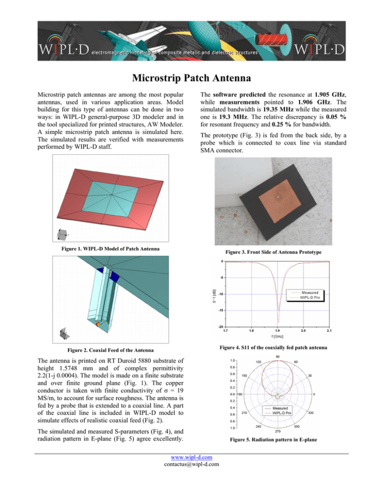
Microstrip Patch Antenna Microstrip patch antennas are among the most popular antennas, used in various application areas. Model building for this type of antennas can be done in two ways: in WIPL-D general-purpose 3D modeler and in the tool specialized for printed structures, AW Modeler. A simple microstrip patch antenna is simulated here. The simulated results are verified with measurements performed by WIPL-D staff. The software predicted the resonance at 1.905 GHz, while measurements pointed to 1.906 GHz. The simulated bandwidth is 19.35 MHz while the measured one is 19.3 MHz. The relative discrepancy is 0.05 % for resonant frequency and 0.25 % for bandwidth. The prototype (Fig. 3) is fed from the back side, by a probe which is connected to coax line via standard SMA connector. Figure 1. WIPL-D Model of Patch Antenna Figure 3. Front Side of Antenna Prototype Figure 4. S11 of the coaxially fed patch antenna Figure 2. Coaxial Feed of the Antenna The antenna is printed on RT Duroid 5880 substrate of height 1.5748 mm and of complex permittivity 2.2(1-j 0.0004). The model is made on a finite substrate and over finite ground plane (Fig. 1). The copper conductor is taken with finite conductivity of σ = 19 MS/m, to account for surface roughness. The antenna is fed by a probe that is extended to a coaxial line. A part of the coaxial line is included in WIPL-D model to simulate effects of realistic coaxial feed (Fig. 2). The simulated and measured S-parameters (Fig. 4), and radiation pattern in E-plane (Fig. 5) agree excellently. www.wipl-d.com contactus@wipl-d.com Figure 5. Radiation pattern in E-plane
