Catalog D757
advertisement
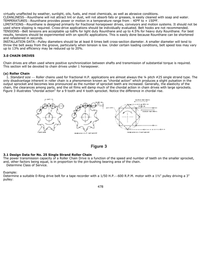
virtually unaffected by weather, sunlight, oils, fuels, and most chemicals, as well as abrasive conditions. CLEANLINESS−−Rounthane will not attract lint or dust, will not absorb fats or greases, is easily cleaned with soap and water. TEMPERATURES−−Rounthane provides power or motion in a temperature range from − 40ºF to + 150ºF. LIMITATIONS−−Rounthane is designed primarily for fractional horsepower drives, conveyors and motion systems. It should not be used where slipping is required. Cross-drive applications should be individually evaluated. Belt hooks are not recommended. TENSIONS−−Belt tensions are acceptable up to8% for light duty Rounthane and up to 4.5% for heavy duty Rounthane. For best results, tensions should be experimented with on specific applications. This is easily done because Rounthane can be shortened and refastened in seconds. INSTALLATION DATA−−Pulley diameters should be at least 8 times belt cross-section diameter. A smaller diameter will tend to throw the belt away from the groove, particularly when tension is low. Under certain loading conditions, belt speed loss may vary up to 13% and efficiency may be reduced up to 20%. 3.0 CHAIN DRIVES Chain drives are often used where positive synchronization between shafts and transmission of substantial torque is required. This section will be devoted to chain drives under 1 horsepower. (a) Roller Chain 1. Standard size −− Roller chains used for fractional H.P. applications are almost always the ¼ pitch #25 single strand type. The only disadvantage inherent in roller chain is a phenomenon known as "chordal action" which produces a slight pulsation in the output sprocket and becomes less pronounced as the number of sprocket teeth are increased. Generally, the elasticity of the chain, the clearances among parts, and the oil films will damp much of the chordal action in chain drives with large sprockets. Figure 3 illustrates "chordal action" for a 9 tooth and 4 tooth sprocket. Notice the difference in chordal rise. 3.1 Design Data for No. 25 Single Strand Roller Chain The power transmission capacity of a Roller Chain Drive is a function of the speed and number of teeth on the smaller sprocket, and, other factors being equal, is in proportion to the pin-bushing bearing area of the chain. Determine Class of Service. Example: Determine a suitable 0-Ring drive belt for a tape recorder with a 1/50 H.P.−−600 R.P.M. motor with a 1½" pulley driving a 3" pulley: 478 Therefore, a Standard 0.210 cross-section 0-ring will be adequate to transmit the load when installed with a 10% stretch. TABLE 14 OVERLOAD SERVICE FACTORS The Overload Service Factors in Table 14 are based on an 8 to 10 hour operating day and the driving unit one of the following types: a. Squirrel Cage Motors−−Normal Torque b. D.C. Motors c. Single Phase Motors If the driving unit is one of the following types, add 0.2 to the foregoing factors: a. Squirrel Cage Motors−−High Torque b. Wound Rotor (Slip Ring) Motors c. Synchronous Motors−−Normal Torque d. Line Shafts and Clutch Starting If the driving unit is one of the following types, add 0.4 to the foregoing factors: a. Synchronous Motors−−High Torque b. Gas, Diesel or Steam Engines For the following special drive conditions, add 0.2 to the foregoing factors: a. 10 to 16 Hour Service b. Speed-Up Drives c. Frequent Starting d. Excessive Moisture e. Abrasive Dust f. Infrequent Maintenance g. Excess Heat h. Centers less than 20 pitches For the following special drive conditions, add .4 to the foregoing factors: 479 a. b. c. d. e. 16 to 24 Hour Service Across the Line Starting Heavy Shock Load Heavy Starting Load Reversing Drives The above factors which apply to a specific drive should be added together to get the total Overload Service Factor. The horsepower of the driver is then multiplied by this total Overload Service Factor to get the Normal Rating of the Drive. "Design Horsepower" Required Design horsepower is the normal horsepower to be transmitted, multiplied by the composite Service Factor selected from Table 14 and corrected with the above correction factor. 3.2 Drive Selection The most economical chain drive selection usually consists of a combination of: a. The shortest pitch single strand chain which has the required "design horsepower" rating when used with the desired size sprocket at the selected sprocket speed. b. The selection of a center-distance that insures a chain wrap of at least 120º (meshing with at least 1/2 of the teeth) on the smaller sprocket. Table 15 indicates the horsepower transmitting capacity of No. 25 single strand chain. These roller chain power transmission ratings are established for chain operation under the following conditions: 1. Service factor of 1. 2. Chain length of 100 pitches. 3. Use of recommended method of lubrication. 4. Two-sprocket drive arrangement. 5. Sprockets aligned and mounted on parallel horizontal shafts. A service life of approximately 15,000 hours may be expected when operated at full rated capacity under conditions as outlined above. TABLE 15 HORSEPOWER RATINGS−−SINGLE STRAND ROLLER CHAIN No. 25 480 TYPE l TYPE ll TYPE lll TYPE lV MANUAL LUBRICATION. Oil applied periodically with brush or spout can. DRIP LUBRICATION. Oil applied between link plate edges from a drip lubricator. OIL BATH or OIL SLINGER. Oil level maintained in casing at predetermined height. OIL STREAM. Oil supplied by circulating pump inside chain The limiting RPM for each lubrication type is read from the column to the right of the boundary lines shown. loop on lower span. 3.3 Sprocket Selection Recommendations Where smooth performance and long service life are desired, sprockets with 17 or more teeth, but less than 67, should be used. On slow speed and special purpose installations or where space limitations are a factor, sprockets with less than 17 teeth can be used. Use of sprockets with more than 67 teeth tends to reduce the normal service-life of the chain. Hardening the smaller sprocket teeth tends to equalize the rate of wear with the large sprocket in the drive. Sprockets should have hardened teeth when any of the following conditions prevail. 1. 2. Sprocket has less than 24 teeth and the rotative speed exceeds 600 R.P.M., or 1/8 of the maximum speed recommended for sprockets with that number of teeth, whichever is smaller. (See horsepower rating, Table 15). The chain speed is approximately 100 feet per minute or less and the chain loading is about 1/7 of the average tensile strength or greater. General experience shows that a sprocket speed ratio between driver and driven sprockets should not exceed about 7:1. 3.4 Selection of Center Distances Quite often the center distance for a roller chain drive is determined within limitations by other machine components or considerations. Although it is not essential that the smaller sprocket have 1200 chain wrap for satisfactory operation and performance, it is recommended as good practice when conditions permit. Chain wrap on the smaller sprocket of a two-sprocket drive with ratio 3.5 to 1 or less, will always be 1200 or more. Chain wrap increases as center distance is increased. For an average application, a center distance of 30 to 50 pitches of chain represents good practice. For pulsating loads, shaft centers as short as 20 pitches of chain may be preferable when sprocket sizes permit. Close attention should be given to proper center distance for the chain length (preferably an "even" number of pitches). 3.5 Chain Drive Selections for Very Slow Speeds Where the linear speed of the chain is to be under 100 feet per minute and the installed chain length exceeds about 50 pitches, roller chains may be selected on the basis of their "endurance limit" and without regard for the customary horsepower ratings. Roller chains selected on this basis are considered primarily as "tension members." The "endurance limit" of a chain is the tensile load which it can accept for an infinite number of cycles without introduction of metal fatigue (failure). Although it is not directly related to the tensile strength, a reasonable approximation of linkplate "endurance limit" (allowable working load is 1/7 of the chain's average tensile strength.) The recommended "endurance limit" of chains with offset links and/or connecting links with slip-fit coverplates is 1/2 of the chain's average tensile strength. Because of their lower capacity, offset links and slip-fit coverplates should be avoided in high load applications, and connecting links with press-fit coverplates should be used. The tensile strength for the chains is given in the product pages as: #25 Hardened Steel−−925 lbs #25 Hardened Steel−−700 lbs 481 Chains selected on the basis of "endurance limit" should be well lubricated to provide satisfactory service life. Although the frequency of chain joint action in such drives is low, and joint wear due to articulation should be low, the lubrication is needed due to the higher loads and to prevent corrosion. Chain Length Calculations Chain Length may be calculated from the following formulae: Where C1 = C2 = L = N n P = = = Center distance in number of pitches (links) −− low ratios and long centers. Center distance in number of pitches (links) −− high ratios and short centers. Chain length in number of pitches (links). Number of teeth in large sprocket. Number of teeth in small sprocket. Chain pitch. If the center distance is already fixed because of other factors, an idler sprocket may be used with not less than a three tooth wrap. When the idler is placed outside the closed span it should be placed nearer the small sprocket, and when inside the closed span it should be placed nearer the large sprocket The 6Z9 series product group in this catalog provides adjustable drive tighteners and idlers. 3.6 Lubrication Chain life will vary appreciably depending on the way the drive is lubricated. A properly lubricated chain can last more than 100 times as long as the same chain with poor lubrication. There are four basic types of lubrication for chain drives. Type l Type ll Type lll −− Manual Lubrication −− Oil should be applied periodically with a brush or spout can, preferably once every 8 hours of operation. −− Drip Lubrication −− Oil drops are to be directed between the linkplate edges from a drip lubricator at a rate of 5 to 20 drops per minute per strand of chain. The higher rate of flow should be applied to chains operating at rotative speeds approaching the limit for drip lubrication as shown on the horsepower rating tables. Precaution must be taken against misdirection of the drops by windage. −− Bath or Slinger Disc Lubrication −− With bath lubrication, the lower strand of chain runs through a sump of oil In the drive housing. The oil level should reach the pitch line of the chain at its lowest point while operating. With slinger disc lubrication, the chain operated above the oil level. The disc picks up oil from the sump and deposits it onto the chain, usually by means of a trough. The diameter of the disc should produce rim 482 Type lV speeds between 600 f.p.m. minimum and 8000 f.p.m. maximum. −− Oil Stream Lubrication −− the oil is sprayed across the lower strand of chain in a continuous stream by a circulating pump or a central lubricating system. 2. Miniature roller chains −− These chains are designed especially for use where space is limited, or where light weight is an important factor. The high strength-to-weight ratio, durability, and extreme dimensional accuracy make this chain ideal for positive power transmission or shaft synchronization where precision and compactness are important. Examples are: communications equipment, business machines, cameras, and other electronic or electro-mechanical devices. For chain speeds not exceeding 100 feet per minute, maximum load on chain should be no more than 20 pounds. For higher chain speeds, maximum chain loading should be reduced depending on the operating conditions: length of service required, sprocket size, number of sprockets in the drive, chain speed, and the length of chain. For sprockets with 20 teeth, or less, speeds should not exceed 15,000 R.P.M. Larger sprockets should be limited to reduce speeds. For example, the speed of 60 tooth sprockets should not exceed 6,000 R.P.M. Lubrication is desirable where high loads, speeds and service life are required. Miniature chain is available from stock and listed in the Product Section of the SDP catalog. (b) Ladder Chain Ladder chain links are fabricated from wire which has been formed so that each link interlocks with its adjacent links to form a continuous chain whose drive members appear as rungs on a ladder. Hence the name; Ladder Chain. Ladder Chain is inexpensive and easy to install. It finds wide use in household appliances, recorders, vending machines and in various timing and electrical devices. Ladder Chains are flexible enough so that in a 2 sprocket drive, one of the sprockets can be rotated well over 90 degrees with respect to the other sprocket plane provided of course that sufficient center distance is allowed. Thus offering a decided advantage over roller chain and timing belts in this regard. Ladder Chains are assembled manually by spreading the connecting loops on the end link slightly apart with a pair of needle nosed pliers, and retightening the loops after engaging the link from the other end of the chain. Table 16 indicates the approximate H.P. ratings of the various chain sizes and material combinations listed in the SDP product catalog. TABLE 16 Chain No. 14 17 18 19 Approx. H.P. Capacity @ 500 RPM Hi-Tensile Basic Brass Steel Steel 1 1/2 1/3 3/4 1/3 1/4 1/2 1/4 1/6 1/3 1/6 1/8 (C) Bead Chain Bead Chain consists of a series of hollow metal beads, linked together by dumbbell shaped wire links. Since the beads are free-to swivel, the chain can be easily-twisted, thus making it extremely versatile for unusual drives. Bead chain because of its construction should only be considered on a low speed or manual drives With low torque requirements. 483
