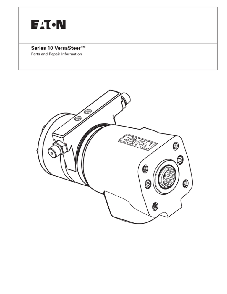
Series 10 VersaSteer™
Parts and Repair Information
Series 10
VersaSteer
Table of Contents
Introduction
ID Tag . . . . . . . . . . . . . . . . . . . . . . . . . . . . . . . . . . . . . . . . . . . . . . . . . . . . . . . . . . . . . . . . . . . . . . . . . . . . . . . . . . . . . . . . . . . . . . . . . . . . . . . . . . . . . . . . . . . . . . . . . . .3
Tools
. . . . . . . . . . . . . . . . . . . . . . . . . . . . . . . . . . . . . . . . . . . . . . . . . . . . . . . . . . . . . . . . . . . . . . . . . . . . . . . . . . . . . . . . . . . . . . . . . . . . . . . . . . . . . . . . . . . . . . . . . . .3
Parts
Assembly Drawing . . . . . . . . . . . . . . . . . . . . . . . . . . . . . . . . . . . . . . . . . . . . . . . . . . . . . . . . . . . . . . . . . . . . . . . . . . . . . . . . . . . . . . . . . . . . . . . . . . . . . . . . . .4
List . . . . . . . . . . . . . . . . . . . . . . . . . . . . . . . . . . . . . . . . . . . . . . . . . . . . . . . . . . . . . . . . . . . . . . . . . . . . . . . . . . . . . . . . . . . . . . . . . . . . . . . . . . . . . . . . . . . . . . .5
Gerotor parts . . . . . . . . . . . . . . . . . . . . . . . . . . . . . . . . . . . . . . . . . . . . . . . . . . . . . . . . . . . . . . . . . . . . . . . . . . . . . . . . . . . . . . . . . . . . . . . . . . . . . . . . . . . . . .6
Disassembly . . . . . . . . . . . . . . . . . . . . . . . . . . . . . . . . . . . . . . . . . . . . . . . . . . . . . . . . . . . . . . . . . . . . . . . . . . . . . . . . . . . . . . . . . . . . . . . . . . . . . . . . . . . . . . . . . . . . .6-10
Assembly . . . . . . . . . . . . . . . . . . . . . . . . . . . . . . . . . . . . . . . . . . . . . . . . . . . . . . . . . . . . . . . . . . . . . . . . . . . . . . . . . . . . . . . . . . . . . . . . . . . . . . . . . . . . . . . . . . . . . .10-16
Seal Installation . . . . . . . . . . . . . . . . . . . . . . . . . . . . . . . . . . . . . . . . . . . . . . . . . . . . . . . . . . . . . . . . . . . . . . . . . . . . . . . . . . . . . . . . . . . . . . . . . . . . . . . . . . . . . . . . .11-12
Introduction
This manual provides service
information for Char-Lynn®
Series 10 VersaSteer™
Steering Control Units. Step
by step instructions for
complete disassembly,
inspection and
reassembly of the control
unit are given.
The following
recommendations should be
followed to insure
successful repairs.
•
Most repairs require the
removal of the control
unit from the vehicle.
•
Cleanliness is extremely
important.
•
Clean the port areas
thoroughly before
disconnecting the
hydraulic lines.
2
•
Plug the control unit
ports and cover open
hydraulic lines
immediately after they
have been
disconnected.
•
Drain the oil and clean
the exterior of the
control unit before
making repairs.
•
Wash all metal parts in
clean solvent.
•
Use filtered, moisturefree compressed air to
dry the parts.
•
Lubricate new rubber
seals with a petroleum
jelly before installation.
•
Torque all bolts over
gasketed joints, then
repeat the torquing
sequence to make up for
gasket compression.
After all repairs are
complete it is essential to
verify the accuracy of control
unit repairs on an
authorized test stand.
Do not wipe them dry
with paper towels or
cloth – lint in a hydraulic
system will cause
damage.
•
Always use new seals
when reassembling
hydraulic control units.
EATON Hydraulics Series 10 VersaSteer Parts and Repair October 2004
ID Tag
Ordering Parts
How to Order
Replacement Parts
Each order must include the following:
1. Product Number
2. Date Code
3. Part Name
4. Part Number
Bar Code Label — Launch Date June, 1999
5. Quantity of Parts
Refer to specific part listings
for your Char-Lynn® VersaSteer™
Steering Control Unit when ordering
replacement parts. Listings
Customer part number
are available from Eaton.
or base unit number if it
Sample tag shows identification.
has a column or valve
When ordering replacement
parts, you must include the
following information:
For additional literature contact
Eaton Hydraulics at
assembled
Eaton Corp. Hydraulics Div.
Eden Prairie, MN 55344
Month / Day / Year
Eaton Part Number
14615 Lone Oak Road,
Eden Prairie, MN 55344
http://hydraulics.eaton.com
Tools
Port Face
Tools Required For Disassembly and Assembly
• Screwdriver (102-152 mm [4 in. - 6 in.] long, x 3 mm [118 in.]
thin flat blade).
• 1/2 inch socket for current hex head cap screws.
• Breaker bar wrench.
• Torque wrench (30 Nm [300 lb-in] capacity).
• 11/16 inch wrench.
Special Tools:
• Plunger and Sleeve
Tool No. 600792-001*
*Tools available—by special order—through our service department.
EATON Hydraulics Series 10 VersaSteer Parts and Repair October 2004
3
Parts
Assembly
Drawing
Low
10, 11
or
6
Medium
or
Standard
3
52
3
Manual Steering
Check Valve
18
3
8b
5
19
8a
7
9
12
60
15
13
14
*
1
Hex Head Screw
13
16
21
2
22
3
86a
56
86
3
55
48
3
85
49
89
86a
21
86
21
88
23
or
25
22
or
53
22
24
23
22
*Anti-cavitation valve parts will vary
according to configuration.
4
EATON Hydraulics Series 10 VersaSteer Parts and Repair October 2004
Parts
Table 1.0 Parts
List
Series 10
VersaSteer
ITEM
NO.
1
2
3
5
6
7
8a
8b
9
10
11
12
13
14
15
16
18
19
21
22
23
24
25
48
49
52
53
55
56
60
85
86
86a
88
89
PART NO.
QTY.
DESCRIPTION
See Table 1.0
23901-000
5776-000
113094-000
4998212-001
204107-XXX
7
1
6
1
1
1
1
1
1
2 or 3
4 or 6
1
Cap Screw, Hex Head
Cap, End
Seal, 72,6 mm [2.86 in.] ID
Plate, Spacer
Drive
Housing, Valve
Control Sleeve
Control Spool
Pin, Centering
Spring, Spacer
Spring, Centering
Retainer Spring
15-000
112714-000
113599-000
112737-000
14880-000
5544-000
9332-000
844-000
16026-422P
285020-080
16026-436
18015-000
230400-000
or 4999516-000
113598-000
230313-000
202038-000
16101-322
4999016-001
4999092-001
4999015-000
See Table 1.0
4999651-001
230397-000
112114-010
250003-906
4998914-001
4992809-001
2
1
1
1
1
1
2
2
2
2
2
2
1
1
1
1
1
1
1
1
2
2
1
1
REFERENCE
PAGE
6
Bearing Race
Bearing, Needle Thrust
Seal – 24,9 mm [.98 in.] ID
Dust Seal
Pin, Roll– 34,92 mm [1.375 in.] Length
Ball – 6,35 mm [.25 in.] OD
Pin, Roll – 40,00 mm [1.575 in.] Length
Ball, Check – 6,35 mm [.250 in.] OD
Compression Spring
Compression Spring (See main parts assembly drawing)
Anti-cav plug retainer
Compression Spring
Ring, Seal
Ring, Back-up
Plate, Valve
Valve S/A
Plate Valve
Gerotor Sub-assembly
O-ring
Spring, Compression
Fitting
O-Ring
Piston
Piston, Guide Spring
6
EATON Hydraulics Series 10 VersaSteer Parts and Repair October 2004
5
Parts
Gerotor
Table 1.0
ACTUAL
DISPL.
cm3/r
[in3/r]
REF. NO. 4
GEROTOR
PART NO.
Width mm[in]
REF. NO. 29
CAP SCREW
PART NO. LENGTH mm[in]
60
75
95
120
145
160
185
230
295
370
460
590
740
201234-023
201234-024
201234-003
201234-009
201234-020
201234-004
201234-005
201234-031
201234-035
201234-008
201234-033
201234-036
8618-034
10,2 [.40]
10,2 [.40]
13,2 [.52]
16,5 [.65]
20,1 [.79]
21,9 [.86]
25,4 [1.00]
31,7 [1.25]
40,4 [1.59]
50,8 [2.00]
63,5 [2.50]
80,8 [3.18]
101,6[4.00]
16336-530
16336-530
16336-531
16336-532
16336-533
16336-534
16336-534
16336-537
16336-541
16336-545
16336-551
16336-556
16336-564
[3.6]
[4.5]
[5.9]
[7.3]
[8.9]
[9.7]
[11.3]
[14.1]
[17.9]
[22.6]
[28.2]
[35.9]
[45.1]
76,2 [3.00]
76,2 [3.00]
79,5 [3.13]
82,6 [3.25]
85,9 [3.38]
88,9 [3.50]
88,9 [3.50]
98,6 [3.88]
104,9 [4.13]
117,6 [4.63]
133,4 [5.25]
146,1 [5.75]
165,1 [6.50]
Disassembly
Cleanliness is extremely
important when repairing a
steering control unit. Work
in a clean area. Before disconnecting lines, clean port
area of unit thoroughly. Use
a wire brush to remove
foreign material and debris
from around exterior joints
of the unit.
1.
Clamp unit in vise,
meter end up. Clamp
lightly on edges of port
face sides (see figure1).
Use protective material
on vise jaws. Housing
distortion could result if
jaws are overtightened.
Gerotor (Meter) End
25 mm
[1 inch]
Max.
We recommend that you
keep the unit in a vise during
disassembly. Follow the
clamping procedures
explained throughout the
manual.
Figure 1
6
EATON Hydraulics Series 10 VersaSteer Parts and Repair October 2004
Disassembly
Screw, Cap, Hex Head
2.
Remove 5/16 in. cap
screws.
3.
Remove end cap.
Cap, End
4.
Remove seal.
Seal
Note: All Series 10
VersaSteer™ steering
control units have a low
slip sealed gerotor
star, this unit inculdes a
ring seal and a back-up
ring.
Low Slip
Seal, Ring
Sealed
Gerotor
Ring, Back-up
Star Only
Gerotor
Figure 2
5.
Remove gerotor (meter).
Be careful not to drop star.
6.
Remove seal from
valve plate.
7.
Remove valve plate.
8.
Remove seal from
valve S/A.
Gerotor
(Meter)
Seal
Valve Plate
Seal
Valve S/A
Figure 3
EATON Hydraulics Series 10 VersaSteer Parts and Repair October 2004
7
Disassembly
Valve S/A
9.
Remove valve Subassembly
10. Remove seal from
valve plate.
11. Remove valve plate
Seal
Valve Plate
Seal
Drive
Figure 4
12. Remove seal from spacer
plate.
Seal
13. Remove spacer plate.
Plate, Spacer
14. Remove seal from housing.
15. Pull drive and twist to
remove SP/SL drive
assembly from housing.
Seal
Attention: Do not bind
spool and sleeve in housing.
Rotate spool and sleeve
assembly slowly when
removing it from housing.
16. Remove housing from vise.
Drive
Drive, Spool, and Sleeve
17. Carefully remove bearing
and races, anti-cavitation
valves and manual
steering check valve
(roll pin and ball) from bolt
holes by tipping housing
Gerotor side down.
(see figure 6).
Housing
Figure 5
8
EATON Hydraulics Series 10 VersaSteer Parts and Repair October 2004
Disassembly
18. Do not remove any
valves other than
manual steering check
valve assembly and
anti-cavitation valve
assembly. All other
valves are factory preset
and are non-serviceable.
Manual Steering
Check Valve
Dust Seal
Ball
Roll Pin
Seal
O-ring
Race
Bearing
19. Carefully Remove Seal with
a thin-blade screw driver.
Do not scratch seal groove
with screw driver.
20. Use thin bladed screw
driver to pry dust seal
from housing. Do not
damage housing.
* Anti-Cavitation Valves
Race
Ball
Roll Pin
for Cylinder Ports
Reference Page 4
for other configurations
Figure 6
21. Push pin from spool and
sleeve assembly.
22. Remove Drive
23. Push spool partially from
control end of sleeve,
then carefully remove
centering springs and
retaining ring from spool
by hand (figure 7).
Standard Input Torque
Spring/Spacer Package
Medium Input Torque
Spring/Spacer Package
*Note
Standard input torque unit
uses six centering springs
and two spacers.
Low Input Torque
Spring/Spacer Package
Medium input torque unit
uses four centering
springs and three spacers.
Low input torque unit
uses four centering
springs and two spacers.
Figure 7
EATON Hydraulics Series 10 VersaSteer Parts and Repair October 2004
9
Disassembly
Fitting
1/4” Hex Key
Piston
24. Disassemble valve sub-assembly as
shown in figure 8.
Valve S/A
O-ring
Piston, Guide Spring
Fitting
Spring, Compression
Figure 8
O-ring
Assembly
Assembly Cleanliness
Recommendations
Check all mating surfaces. Replace any parts that have scratches or burrs that could cause leakage. Clean all metal parts in
clean solvent. Blow dry with air. Do not wipe dry with cloth or paper towel because lint or other matter can get into the
hydraulic system and cause damage. Do not use grit paper or file or grind these parts.
Note: Lubricate all seals with clean petroleum jelly. A good service policy is to replace all old seals with new seals. Do not
use excessive lubricant on seals for meter section.
Refer to parts lists covering your steering control unit when ordering replacement parts.
Fitting
Piston
1. Reassemble valve parts
with new o-rings on
plugs (See figure 9).
Valve S/A
O-ring
Torque Fittings to
31-45Nm [23-33 lb-ft]
Piston, Guide Spring
Fitting
Spring, Compression
O-ring
*Note: The fittings included in the
valve assembly are critical in
the operation of the valve,
and must not be switched
with another style.
Figure 9
10
EATON Hydraulics Series 10 VersaSteer Parts and Repair October 2004
Assembly
2.
Place housing on a flat
work area on a clean lint
free cloth.
Install press-fit
24,9 mm[.98 in.] ID seal
in housing with metal
suface of seal facing
toward housing (figure 10).
Figure 10
2-Piece Shaft Seal
Installation
For installation of
o-ring: 4999651-001
and
Seal 9332-000
1.
Place housing on a flat
work area as shown in
figure 11.
2.
Lubricate seal and o-ring
with hydraulic oil before
installation
3.
Align sleeve with
housing bore (figure 11)
4.
Insert sleeve into
housing bore (Figure 12)
5.
Place o-ring on plunger
Figure 11
Tool No. 600792-001
(Figure 13).
Figure 12
Figure 13
EATON Hydraulics Series 10 VersaSteer Parts and Repair October 2004
11
Assembly
2-Piece Shaft Seal
Installation
6.
Align seal with plunger.
cross section "L" shape
of seal should be upside
down (figure 14).
12. Inspect seal
installation. Seal
and o-ring must
both be within
shaft seal counter
bore of housing
(figure 18).
Figure 18
Figure 14
7.
Push seal onto plunger.
Lip of seal should be
between o-ring and
plunger. No gap should
exist between o-ring
and seal (figure 15).
25mm[1in]
13. Clamp housing in vice
(figure 19).
Figure 15
8.
Align plunger with
sleeve (figure 16).
9.
Push plunger into sleeve
until it bottoms out,
rotate 1/4 turn
(figure 17).
Figure 19
14. Install two bearing races
and thrust bearing as
shown in figure 20.
10. While holding sleeve in
housing, withdraw
plunger.
11. Withdraw sleeve.
Needle Thrust Bearing
Bearing Race
Figure 16
Figure 17
12
EATON Hydraulics Series 10 VersaSteer Parts and Repair October 2004
Figure 20
Assembly
Spring Slot
15. Assemble spool and
sleeve carefully so that
spring slots line up at the
same end. Rotate spool
while sliding parts
together. Test for free
rotation. Spool should
rotate smoothly in sleeve
with fingertip force
Control Spool
applied at splined end.
Align spring slots and
identification marks
(Figure 21) in spool and
sleeve and stand parts on
end of bench.
Control Sleeve
Identification Marks
Figure 21
2
16. Installation of spring
spacers and springs, hold
spring retainer at an angle
as shown (see figure 22
reference number 1),
insert spring spacers and
springs one at a time in
sequence noted by
reference numbers 2 - 9
(standard torque), 2 - 8
(medium torque), 2- 7 (low
torque), then position
spring retainer correctly
over all these parts.
Adjust alignment of
spring parts with a
small screwdriver.
Standard
Torque
4
6
Spring Spacer
Springs
8
9
7
1
5
3
Spring Spacer
2
4
Medium
6 Torque
8
7
5
3
2
4
Low
6 Torque
7
5
3
Figure 22
EATON Hydraulics Series 10 VersaSteer Parts and Repair October 2004
13
Assembly
17. Assemble drive and
spool/sleeve.
18. Insert pin through spool
and sleeve assembly
through hole in drive,
until pin is flush at both
sides of sleeve.
Note: Check to insure that
spool and sleeve are flush or
slightly below 14 hole surface
of housing.
Attention: Clean upper surface
of housing by wiping with palm
of clean hand. Clean each of
the flat surfaces of meter section parts in a similar way just
before reassembly. Do not use
cloth or paper to clean surfaces.
Pin
Figure 23
19. Position spool and sleeve
assembly so that splined
end of spool enters 14
hole end of housing first
(figure 23).
Attention: While inserting
spool and sleeve assembly
into housing, make sure parts
do not tilt out of position.
Push assembly gently into
place with slight rotating
action. Bring spool assembly
entirely within housing bore
until parts are flush at 14 hole
end of housing. With spool
assembly in this flush
position, check for free
rotation within housing by
turning assembly with
fingertip force at splined end.
Figure 24
20. Install 72,6 mm [2.86 in.]
ID O-ring in housing
(figure 25).
21. Install anti-cavitation
valves and manual
steering check valve (if
used) in holes, as shown
in figure 25. After
installing balls, inspect
holes to make sure they
are properly seated.
Roll Pin (2)
40,00 mm
[1.575 in.] L
* Anti-Cavitation Valves
for Cylinder Ports
See page 4 for other
configurations
Ball (2)
4,762 mm
[.1875 in.] OD
Roll Pin (1)
34,92 mm
[1.375 in.] L
Ball 6,35 mm
[.250 in.] OD
O-ring
Figure 25
14
EATON Hydraulics Series 10 VersaSteer Parts and Repair October 2004
Manual Steering
Check Valve
Assembly
Seal
22. Install spacer plate.
Align bolt holes in spacer
plate with tapped holes
in housing.
23. Lubricate and install 72,6
mm [2.86 in.] ID seal in
spacer plate.
Valve Plate
Seal
Valve S/A
24. Install valve plate.
25. Lubricate and install 72,6
mm [2.86 in.] ID seal in
valve plate.
26. Install valve S/A,
see figure 26 for correct
position.
Seal
Valve Plate
Seal
27. Lubricate and install 72,6
mm [2.86 in.] ID seal in
valve S/A.
Spacer Plate
28. Install valve plate.
Housing
Alignment
Reference —
Bolt Hole
on Center
(Port Face
Side)
29. Lubricate and install 72,6
mm [2.86 in.] ID seal in
valve plate.
30. Install gerotor, seal
groove up; note position
of star valleys in relation
to marked drive.
Figure 26
Timing Reference Data —
Align star valley (reference A) with
marked drive (reference B). Valley
must align with pin. Note parallel
relationship of reference lines A, B,
C, and D in figure 27. Align bolt
holes without disengaging gerotor
(meter) from drive.
A
Meter
(Gerotor
Star Valley
Gerotor
Seal
Valve Plate
B
Seal
Drive
(Marked)
C
Valve S/A
Pin
Figure 27
EATON Hydraulics Series 10 VersaSteer Parts and Repair October 2004
15
Assembly
31 Install back-up ring and seal
ring in gerotor star.
Screw, Cap, Hex Head
32. Lubricate and install 72,6 mm
[2.86 in.] ID seal in gerotor
(meter).
Cap, End
33. Install end cap on gerotor,
aligning holes.
Seal
Low Slip
Sealed
Gerotor
Star
Seal, Ring (metal)
Ring, Back-up (rubber)
Gerotor
Groove cross section
w/ rings
Figure 28
34. Install 7 dry cap screws in
end cap. Pretighten cap
screws to 17Nm [150 lb-in],
then torque screws to
28-34 Nm [250-300 lb-in] in
sequence shown in
figure 29.
6
4
1
2
7
3
5
Figure 29
Eaton
14615 Lone Oak Road
Eden Prairie, MN 55344
USA
Tel: 952 937-9800
Fax: 952 974-7722
www.hydraulics.eaton.com
Eaton
20 Rosamond Road
Footscray
Victoria 3011
Australia
Tel: (61) 3 9319 8222
Fax: (61) 3 9318 5714
Eaton
Dr.-Reckeweg-Str. 1
D-76532 Baden-Baden
Germany
Tel: (49) 7221 682-0
Fax: (49) 7221 682-788
© 2005 Eaton Corporation
All Rights Reserved
Printed in USA
Document No. C-STCU-TS006-E
June 2005

