Receiver with preamp.
advertisement
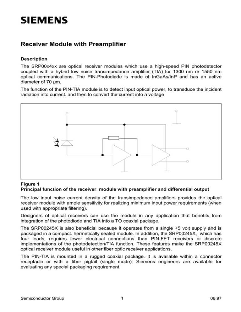
Receiver Module with Preamplifier Description The SRP00x4xx are optical receiver modules which use a high-speed PIN photodetector coupled with a hybrid low noise transimpedance amplifier (TIA) for 1300 nm or 1550 nm optical communications. The PIN-Photodiode is made of InGaAs/InP and has an active diameter of 70 µm. The function of the PIN-TIA module is to detect input optical power, to transduce the incident radiation into current. and then to convert the current into a voltage Figure 1 Principal function of the receiver module with preamplifier and differential output The low input noise current density of the transimpedance amplifiers provides the optical receiver module with ample sensitivity for realizing minimum input power requirements (when used with appropriate filtering). Designers of optical receivers can use the module in any application that benefits from integration of the photodiode and TIA into a TO coaxial package. The SRP00245X is also beneficial because it operates from a single +5 volt supply and is packaged in a compact. hermetically sealed module. In addition, the SRP00245X, which has four leads, requires fewer electrical connections than PIN-FET receivers or discrete implementations of the photodetection/TIA function. These features make the SRP00245X optical receiver module useful in other fiber optic receiver applications. The PIN-TIA is mounted in a rugged coaxial package. It is available within a connector receptacle or with a fiber pigtail (single mode). Siemens engineers are available for evaluating any special packaging requirement. Semiconductor Group 1 06.97 Receiver Module with Preamplifier Advantages The SRP00245X provides significant benefits over hybrid designs and 14-pin receivers. Integration of the transimpedance amplifier with the PIN detector into the TO can reduces parasitic capacitances and lead inductances. These reductions improve sensitivity over that attainable by designs that place the amplifier outside the can. away from the detector. The SRP00245X, which has four pins, is advantageous over 14-pin receivers because it requires less board space. In addition, the SRP00245X operates from a single +5 volt supply, whereas typical optical receivers need at least two supplies. The reduction of board space and need for just a single supply make for a less expensive, higher performance alternative to other kinds of optical receivers. External Circuitry Requirements When designing the SRP00245X into an optical receiver, the engineer should observe standard high speed PC board design practices. For example, we urge bypassing of the power supply so as to reduce noise that appears at the output of the PIN-TIA. To eliminate oscillations, we recommend mounting the PIN-TIA on a circuit board with a large, low impedance ground plane. Ensure proper RF grounding by connecting the case lead to the electrical ground. In addition, shorten the length of all the module leads so as to reduce excess inductances. Noise Filter PIN-Transimpedance Amplifier AC coupling Output Amplifier Figure 2 Combination of the PIN-Transimpedance amplifier with an output amplifier ECL line receivers can be used as output amplifier. Depending on the gain two amplifiers may be needed to get a limited ECL-signal with the minimum received power. Semiconductor Group 2 Receiver Module with Preamplifier Signal path If signal traces are relatively long, use impedance matching techniques to maximise power transfer from the PIN-TIA to its load: for microstrip design. use 50 Ω as the output impedance of the PIN-TIA. AC Coupling Note as well that the output of the PIN-TlA is DC coupled. Since most applications require AC coupled stages, the engineer should place a high Q RF chip capacitor on the output of the module. The capacitance has to be high enough to avoid problems with the high pass characteristic of the receiver. If both outputs are used (recommended) two capacitors are needed. Noise Filtering The bandwidth of the PIN-TIA may be greater than that required for receiving the data rate required in the system. For example the SRP00245X has a minimum bandwidth of 280 MHz, whereas reception of an STM-1 transport necessitates a bandwidth of just 70% of the 155.52 Mb/s rate. Any frequency component above this bandwidth contributes excess noise to the output and reduces the sensitivity. Therefore a low pass with about 100 MHz has to placed between the analogue output of the PIN-TIA and the input of the limiting output amplifier. If both outputs are used (recommended) two noise filter are needed or the noise filter can be placed between the two outputs. Description of the TIA Transimpedance amplifiers have been widely used as the preamplifier in fiber-optic receivers. On request different ICs are applicable. They are characterized by following parameters: • Bandwidth (maximum datarate) • Sensitivty (minimum needed optical power for the specified BER) • Transimpedance and dynamic range (maximum applicable optical power) • Differential output or single ended • Power consumption Semiconductor Group 3


