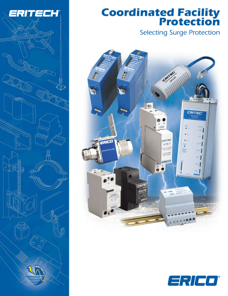
Coordinated Facility
Protection
Selecting Surge Protection
Introduction
By following the Six Point Plan of Protection, ERICO®
customers are able to implement the most effective
solutions to individual lightning, grounding and surge
problems while retaining an integrated protection
philosophy.
The Six Point Plan of Protection from ERICO
Point 5 of the Six Point Plan advocates a coordinated
approach to surge protection, where the first stage of
defense is the installation of primary protection devices at
the mains supply service entrance, followed by secondary
protection at distribution branch panels and where
necessary, at point-of-use applications.
Point 6 recognizes the need to provide effective surge
protection on cables supplying telecommunications,
signal and data management equipment.
Capture the
lightning
strike
ERITECH® SYSTEM 2000
Conventional Lightning
Protection System
ERITECH® SYSTEM 3000
Active Lightning
Protection System
Direct Lightning Strike
Telephone Lines
Overhead
Distribution
Voltage
Transmission
Lines
Protect Low Voltage
Data/Telecommunications
Circuits
AC Transformer
Sub Station
PCS,
Radio &
Telemetry
Equipment
IS
File
Server
Signal Control
Lines
Telephone Main
Distribution
Frame
Billing Printer
Computer
Power
Distribution Panel
Induced Surge
PABX
Protect
Incoming AC
Power Feeders
Inverter
Rectifier
Power Ground
Safely Convey
Energy to
Ground
TVSS
Batteries
Remote
Data
Terminal
Inspection Well
Ground Potential
Equalization Bonding
Low Impedance Ground
using flat copper radials
Ground Enhancement
Material
Dissipate Energy
into the
Grounding
System
2
Bond All
Ground Points
Together
Sub-Distribution
Board
Power Protection TVSS Device
Communications Line Protection Device
Ground Electrode
www.erico.com
The Need for Coordinated Protection
Critical Factors
Critical factors need to be considered when determining the need for facility
protection. Many factors can be determined by answering the following
questions:
• What is the risk to personnel?
• What is the risk of equipment damage?
• What are the consequences of equipment failure?
• Is the equipment associated with an essential service?
• How will equipment failure affect overall facility operation and revenue
generation?
• What are the legal implications of providing inadequate protection?
The statistical nature of lightning and the broad spectrum of energy delivered
by a lightning flash, the problems created by various power generation and
distribution systems, and the continued trend to more sensitive and specialized
electronics, requires careful selection of available technologies if adequate
protection is to be provided.
What are the costs of inadequate protection?
According to Holle, et al., Journal of Applied Met, Vol
35, No.8, August 1996: Insurance claims to lightning and
over-voltage damage amount to US$332 million annually in
the US. On average this represents one claim for every 57
lightning strikes in the US.
Sources of Transients and Surges
Although lightning is the most spectacular form of
externally generated surges, it is only one source of overvoltage. Other sources include the switching of power
circuits, the operation of electrical equipment
by neighboring industries, the operation of power factor
correction devices, and the switching and clearing of faults
on transmission lines. It is important to note that lightning
does not need to directly strike a power line for such
damage to occur; a strike several hundred meters away
can induce large damaging transients, even to
underground cables.
The costs that can result from inadequate protection
are many and varied. The type of equipment within a
facility will have a direct impact on the damage that
can occur. Robust equipment, such as lighting and
air-conditioning systems, are often able to withstand
impulses as high as 1500 volts and are not as sensitive
to the rapid rate-of-rise exhibited by the pre-clamped
surge waveform as are electronics. These systems are
often not critical to the continuing operation of the site
and therefore usually do not require the premium level
of protection that is essential for more sensitive
equipment.
It is estimated that 70 to 85% of all
transients are generated internally
within one’s own facility by the
switching of electrical loads such as
lights, heating systems, motors and
the operation of office equipment.
However, significant damage can occur, even to the
more robust systems, as a result of lightning induced
surges resulting within a radius of several kilometers,
or from switching induced surges.
Costs can range from degradation of electrical or
electronic systems to data loss, equipment destruction
or injury to personnel. Some of these costs can appear
relatively minor but the loss of an essential service or
revenues associated with a facility or plant shut down
can be enormous.
Damage to vital equipment caused
by destructive
surges and transients.
According to the Insurance Information Institute, NY,
(NY Press Release 11 August 1989): Lightning and
over-voltage transients cause damage to property,
electrical, electronic and communications equipment estimated to
be more than US$1.2 billion dollars per year in the US alone. This
represents approximately 5% of all insurance claims in the US.
Costs in more lightning prone regions of the world are even greater.
www.erico.com
Modern industry is highly reliant
on electronic equipment and
automation to increase productivity
and safety. The economic benefits
of such devices are well accepted.
Computers are commonplace and
microprocessor-based controllers
are used in most manufacturing
facilities. Microprocessors can also be
found embedded in many industrial
machines, security & fire alarms, time
clocks and inventory tracking tools.
Given the wide range of transient
sources and the potential cost of
disruption, the initial installed cost
of surge protection can readily be
justified for any facility.
As a guide, the cost of protection should be approximately
10% of the cost of the facility’s economic risk.
3
The Need for Coordinated Protection
an air terminal on the facility may capture the lightning energy but without
a dependable ground system, this energy cannot be safely dissipated.
Equally, even the most expensive Surge Protection Devices (SPDs) are poor
performers if a low impedance equipotential ground is not provided. These
interdependent disciplines are best applied when looking at a total facility
rather than at an individual piece of equipment or portion of the facility.
Reliable protection of structures, industrial and commercial
operations and personnel, demands a systematic and
comprehensive approach to minimizing the threats
caused by transient over-voltages. Grounding, bonding,
lightning protection and surge protection all need to be
considered for comprehensive facility electrical protection.
Each of these are interdependent disciplines that need
a holistic design approach to ensure the facility is not
left with a vulnerable “blind spot”. The investment in
surge protection can be wasted if “blind spots” exist.
For example, installing a surge protection device on the
power supply to a programmable logic controller is of little
value if the I/O lines are not also protected. In addition,
Lightning protection principles
recommend that all external cabling
enter the building at a common point.
It is for these reasons that ERICO® developed the Six Point Plan of Protection.
The plan prompts the consideration of a coordinated approach to lightning
protection, surge and transient protection and grounding, an approach that
embraces all aspects of potential damage, from the more obvious direct
strike to the more subtle mechanisms of differential earth potential rises and
voltage induction at service entry points.
Line Surge
Protectors
(LSPs)
Remote
Sensor
Control
WEIGH BRIDGE
Load Cell
Protector
Program
Logic
Controller
CENTRAL PROCESS
MONITORING
FACILITY
Load Cell
Protector
Universal
Transient
Barriers
PR
OG
RA
CO LOGI M
NT C
RO
LLER
DINLINE
Surge Filter
UTB
Ground
Ground
Ground
Ground
Telephone
Line
Potential
Equalization
Clamp
DINLINE
Surge
Surge Filter
Reduction
Filter
Universal
Transient
Barriers
Distribution
Board
Overhead
High Voltage
Transmission
Lines
Ground
Ground
Ground
AC Transformer
Sub Station
MANUFACTURING FACILITY
Ground
Where building facilities are
separated by less than 30 metres,
building grounding systems should
be bonded together.
The Six Point Plan applied to a manufacturing facility. Surge and transient protection principles applied to a total facility rather than individual pieces of equipment.
4
www.erico.com
Selecting Surge Protection
RECOMMENDED SURGE RATINGS (8/20µs)
CAT C
ANSI/IEEE C62.41
CAT B
CAT A
IEC 61643 Test Class
I
I, II
II
III
VDE Classification
A
B
C
D
POINT-OF-ENTRY
HIGHLY EXPOSED OR
CRITICALLY IMPORTANT
SITES
POINT-OF-ENTRY
EXPOSED OR RURAL
SITES
POINT-OF-ENTRY
INNER CITY SITES
DISTRIBUTED CIRCUITS,
POWER OUTLETS,
CIRCUITS REMOTE
FROM POINT-OF-ENTRY
SUB CIRCUITS OR
NEAR TO
POINT-OF-ENTRY
EXPOSURE
HIGH Ng >2
100kA
70kA
40kA
20kA
10kA
MED. Ng 0.5-2
65kA
40kA
20kA
20kA
5kA
LOW
65kA
40kA
15kA
5kA
3kA
Ng =
Ng <0.5
strikes/km2/year.
RECOMMENDED PRODUCTS
PRODUCT SERIES
SES200
SES40 120/240
TDS Movtec & MPM
TDX200
TDX100
TDX50
TSG - SRF
TSG / SGD
DSD1150
TDS / DSD1100
DSD160 & DSD380
TDS / DSD140 & TDS / DSD340
TDS130
DSD110
TDF
DSF6A
www.erico.com
5
Selecting Surge Protection
Recommended Surge Ratings –
A Comparison between IEC® and IEEE®
Recommendations
Lightning terminal
collection volume
Competition between SPD manufacturers has seen everincreasing surge ratings being offered to the market, to the
point where surges of this magnitude are unlikely to ever occur
in nature. A number of sources provide information on the
statistical distribution of the current discharge of the direct
lightning strike. Many studies have shown that peak lightning
discharges above 100kA are likely to occur less than 5% of
the time. Combined with the fact that most discharges do not
strike the power line directly but are magnetically or capacitively
coupled to it, and that even under a direct lightning discharge
the energy will split in either direction and be attenuated by
the distribution arresters and line losses, it is not difficult to
determine that a smaller fraction of the initial lightning energy
typically enters the facility in question.
LPZ 0A
Protection zones defined by specific product application.
As it can be shown, protection equipment
for power supply systems are classified
as follows, according to its task
• Lightning Current Arrester
• Over-voltage Arrester
Lightning current equipotential bonding arresters must be capable of
conducting a portion of the lightning current without being destroyed.
Over-voltage arresters are only used for limiting over-voltages at
relatively smaller surge currents. The different “protection zones”
assume the division of the initial lightning current, from zone 0 to
higher zones. For zone 0, it is required for the user to select the
lightning protection class, from I - IV : (i.e. these refer to maximum
energy within a direct lightning strike).
Zone subject to direct strikes
Zone not subjected to direct strikes, but unattenuated electromagnetic fields may occur.
Zone not subjected to direct strikes and where
currents in this zone are reduced compared to
Zone OB
Protection Level
Current Magnitude
% Exceeded
Level I
200kA (10/350µs)
~ 0.2%
Level II
150kA (10/350µs)
~ 1.5%
Level III - IV
100kA (10/350µs)
~ 3%
The above levels can be selected based on the statistical level of
protection required. A lightning current of 200kA (10/350µs) can be
expected for the Protection Level I. This lightning current is divided as
follows in the most exposed sites:
LPZ 2... If further reductions in current from LPZ 1 are
achieved/required further zones can be created.
Actual surge ratings required in each of these zones is not
exactly defined and is largely determined by some sitespecific details. However, to assist with this the VDE0675
Part 6 standard defines the minimum class of product that
can be applied to each of these Zones as shown below:
50% (100kA, 10/350µs) discharges via the ground system.
50% (100kA, 10/350µs) flows into the supply systems connected to it,
via the three phase equipotential bonding lightning arresters.
On the other hand IEEE has adopted a Scenario II event, in which the
building lightning protection system is subjected to a direct strike and
the energy level sustained by the equipotential bonding surge arrester(s)
is taken to be 10kA (10/350µs) or approximately 100kA 8/20µs as a
worst case.
Class A : Arrester for use in low-voltage overhead lines
Class B :
LPZ 1
LPZ 2
A “Zone” is where the lightning electromagnetic environment
can be defined/controlled. The zones are characterized by
significant changes of electromagnetic conditions at these
boundaries. These will typically be building boundaries, or the
point where protection is installed.
LPZ 0B
Shielded
Room
ANSI®/IEEE standard C62.41 has classified the “point-of-entry”
environment as CAT. B/C. Under this classification the highest
expected energy level is 10kA 8/20µs. In contrast, the IEC61312
and DIN VDE 0675 defines some differing guidelines. IEC
61000-5-6 and IEC 61312-1 describe protection zone concepts.
This is similar in nature to the ANSI/IEEE C62.41 concept of
Category A, B & C locations.
LPZ OA
LPZ OB
LPZ 1
LPZ 0A
Arrester for lightning current equipotential
bonding (must withstand 100kA 8/80µs or
10As charge, twice). Zones OB to 1 (Main
distribution Boards, Sub-Boards)
If we adopt IEC or DIN VDE Standard and assume a level of III-IV
lightning protection system, each equipotential bonding surge arrester
connected to a three phase, four wire, power system is assumed to
experience a 12.5 kA (10/350µs) energy level at the Zone 0 interface
due to lightning current sharing.
Class C : Arrester for over-voltage protection (must have
a nominal surge rating of at least 5kA 8/20µs)
Zones 1 to 2 (mainly sub-boards or low exposure
main boards)
Class D :Arrester for portable use on socket-outlets
(must have a nominal surge rating of at least
1.5kA 8/20µs)
6
www.erico.com
A Guide to Common Power Distribution Systems
Throughout the world a number of different power distribution
systems are used. This guide identifies the more common of
Description
these systems. The individual product specification tables detail
system suitability.
Source
Configuration
Typical Supply
Voltages
Single Phase
1Ph, 2W+G
110V
120V
220V
240V
Single Phase
1Ph, 3W+G
Also known as Split phase or
Edison system
120/240V
Three Phase WYE
without neutral
3Ph Y, 3W+G
480V
Three Phase WYE
with neutral
3Ph Y, 4W+G
Delta
High leg
3Ph ∆, 4W+G
Delta Ungrounded
3Ph ∆, 3W+G
Delta
Grounded corner
3Ph ∆, 3W+G
www.erico.com
7
(L-N)
(L-N/L-L)
(L-L)
120/208V
220/380V
230/400V
240/415V
277/480V 347/600V
(L-N/L-L)
120/240V
(L-N/L-L)
240V
480V
(L-L)
240V
480V
(L-L)
A Guide to Common Power Distribution Systems
The IECSM 60364 series of standards characterizes low-voltage distribution
systems by their grounding method and the arrangement of the neutral and
protective earth conductors. The selection of SPDs must consider among
other issues, the level of over-voltage that may temporarily occur within the
distribution system due to ground faults. IEC 61643-12 details the temporary
over-voltages that may occur during fault conditions for these systems. To
conform with European wiring rules an SPD with a Uc rating equal to, or
greater than, this value should be selected. Effective protection does not
require SPD s to be installed in all the modes detailed. The following diagrams
provide guidance on the selection and installation of SPDs on the more
common distribution systems. While three phase WYE systems are shown,
similar logic can be applied to single phase, delta and other configuration
sources.
TN-C System
TN-S System
The neutral and protective earth conductor combine in a single conductor
throughout the system. All exposed-conductive-parts are connected to the
PEN conductor.
Main
Distribution Board
Sub/Branch
Distribution Board
* Install fuse A if supply fuse B
exceeds back-up overcurrent
protection rating
* Install fuse C if supply fuse D
exceeds back-up overcurrent
protection rating
Source
Uo = Line to neutral voltage of the system
Un = Nominal country specific system voltage (typically Uo x 1.10)
A separate neutral and protective earth conductor are run throughout. The
protective PE conductor can be the metallic sheath of the power distribution
cable or a separate conductor. All exposed-conductive-parts of the installation
are connected to this PE conductor.
Source
Main
Distribution Board
* Install fuse A if supply fuse B
exceeds back-up overcurrent
protection rating
Sub/Branch
Distribution Board
* Install fuse C if supply fuse D
exceeds back-up overcurrent
protection rating
SPDs shown connected L-N and N-PE.
May also be connected L-PE and N-PE.
TN-C-S System
TT System
A separate neutral and protective earth combine in a single PEN conductor.
This system is also known as a Multiple Earthed Neutral (MEN) system and
the protective conductor is referred to as the Combined Neutral Earth (CNE)
conductor. The supply PEN conductor is earthed at a number of points
throughout the network and generally as close to the consumer’s
point-of-entry as possible. All exposed-conductive-parts are connected to the
CNE conductor.
A system having one point of the source of energy earthed and the exposedconductive-parts of the installation connected to independent earthed
electrodes.
Source
Main
Distribution Board
* Install fuse A if supply fuse B
exceeds back-up overcurrent
protection rating
Sub/Branch
Distribution Board
Main
Distribution Board
Sub/Branch
Distribution Board
* Install fuse A if supply fuse B
exceeds back-up overcurrent
protection rating
* Install fuse C if supply fuse D
exceeds back-up overcurrent
protection rating
Source
* Install fuse C if supply fuse D
exceeds back-up overcurrent
protection rating
SPDs shown connected L-PE and N-PE.
May also be connected L-N and N-PE.
8
www.erico.com
A Guide to Common Power Distribution Systems
IT System
A system having no direct connection between live parts and earth but all
exposed-conductive-parts of the installation being connected to independent
earthed electrodes.
Distribution Network Configuration
TN-C
TN-S
TN-C-S
TT
Between
IT
IT
with
neutral
conductor
without
neutral
conductor
Phase (line) and
Neutral Conductor
X
1.45 Uo
1.45 Uo
1.45 Uo
X
Each Phase (line)
Conductor and PE
X
1.45 Uo
√3 Uo
√3 Uo
√3 Uo
Neutral Conductor
and PE
X
Uo
Uo
Uo
Uo
Each Phase (line)
Conductor and PEN
1.45 Uo
X
X
X
X
SPD Uc Selection:
Uo = Voltage between phase (line) and neutral conductor
X = Not applied
SPD selection must consider the level of over-voltage that may occur within
the distribution system due to ground faults. The above IEC® table shows
over-voltages that may occur during fault conditions for the various systems.
An SPD with a Uc equal or greater than this value should be selected.
Metal Oxide Varistors (MOVs)
Other Symbols
Gas Discharge Tubes (GDTs)
T
Two terminal
gas arrester
Conventional
MOV
With thermal
disconnect
With overcurrent
fusing
Three terminal
gas arrester
With Transient
Disciminating
Technology
T
www.erico.com
9
With failsafe
device
Spark Gap
Triggered
Spark Gap
Silicon
Protection
Audible
Alarm
Glossary of Terminology
8/20μs Current Waveshape
A current impulse with a virtual front time of 8μs and a time
to half-value of 20μs.
Leakage Current
The current flowing to the ground conductor when the SPD is
connected to the nominal supply voltage Un.
Aggregate Surge Rating
The sum of the surge ratings of individual voltage limiting
components, connected in parallel, in the device.
Let-through Voltage
Another term often used to describe the measured limiting
voltage.
Note: This figure does not indicate the maximum discharge current (Imax) of
the device. It does however provide an indication of the expected SPD life.
Users should be aware that certain manufacturers may incorrectly claim the
aggregate surge rating of MOV material used in their device as its Imax. Nonperfect current sharing between parallel MOVs, and the inability of series
over-current or thermal disconnects to carry the full surge current, generally
means that the maximum discharge current which the SPD can withstand is
less than its aggregate surge rating.
Note: This measurement may be carried out with, or without, the presence of the
nominal AC power (Un) being applied to the SPD. As such, the results may be
different and the user should take cognizance of this in making any comparative
assessments.
Attenuation
The ability of an SPD to reduce electrical noise interference,
measured in decibels. Attenuation varies with frequency,
so it is usual to specify the attenuation of the SPD at a
particular frequency; commonly 100kHz.
Note: The user should be aware that international consensus has not
been reached on these classifications, nor on the size of expected
surge activity, which may occur. Further, the user should note that the
demarcation of these zones do not form literal boundaries, but are rather
a gradual transition.
Location Categories
Various standards attempt to define the electrical environment at
which an SPD may be installed, into location categories or zones.
Maximum Continuous Operating Voltage (Uc)
The maximum r.m.s. or d.c. voltage which may be continuously
applied to the SPD’s mode of protection without degradation or
inhibiting its correct operation.
Backup Overcurrent Protection
An external overcurrent protective device installed prior to
the SPD. Such a device may be required if the overcurrent
limiting device on the service is larger than that required by
the SPD or connecting wiring.
Note: Specifications given in the catalog generally are phase (L-N) voltages.
Class I test
SPD tested with maximum impulse current (Iimp) and
nominal discharge current (In).
Maximum Discharge Current (Imax)
The maximum single shot current, having an 8/20μs waveshape,
which the SPD can safely divert.
Class II test
SPD tested with maximum discharge current (Imax) and
nominal discharge current (In).
Measured Limiting Voltage
The maximum voltage measured across the SPD’s terminals
during the application of an impulse of specified waveshape and
amplitude.
Class III test
SPD tested with combination wave
Modes of Protection
SPDs may provide protection line-to-ground, line-to-neutral,
neutral-to-ground or in combinations thereof. These paths are
referred to as the modes of protection.
Distribution System
Defines the electrical power distribution system. The
distribution system is usually described by configuration of
the phases, neutral and ground conductor configuration on
the secondary side of the supply transformer. Refer to pages
10-12 for further information.
Note: The user is advised that not all modes require protection, and more is not
necessarily better when selecting an SPD. As an example, the N-G mode is not
required when the SPD is installed at the primary service entrance of a TN-C-S
electrical distribution system, due to the Neutral-Ground bond at this point. The L-L
mode is generally not provided for systems with neutral conductors since the L-N
modes also protect the L-L modes. Similarly, the L-G mode can be protected via the
L-N and N-G modes.
Follow Current (If)
The current supplied by the electrical power distribution
system which flows through the SPD after a discharge
current impulse. The follow current is significantly higher
than the operating current, and is normally high for voltage
switching type SPDs (e.g. spark gaps) since the arc voltage
falls below the AC supply voltage after firing.
Nominal Discharge Current (In)
The peak value of the current flowing through the SPD during
the application an 8/20μs waveshape.
Note: IEC 61643-1requires SPDs tested to Test Class II, to withstand 15 impulses at
In followed by 0.1, 0.25, 0.5, 0.75 and 1.0 times Imax.
Nominal (System) Voltage (Un)
The L-N voltage by which an electrical power system is
designated. Under normal system conditions, the voltage at
the supply terminals may differ from the nominal voltage as
determined by the tolerance of the supply system (normally +/10%).
Impulse Current (Iimp)
Peak impulse current withstand with a 10/350μs current
waveshape. This is often used for the classification of
SPDs tested to Test Class I, but is not the only acceptable
waveshape.
Insertion Loss
The insertion loss of an SPD is usually only stated for two
port devices for use on low voltage data systems. It is a
measure of the ratio of voltage at the output to the input at
the device under test. The insertion loss is usually stated for
a given frequency and measured in decibels.
One-port SPD
An SPD connected in shunt (parallel) with the circuit to be
protected. A one port device may have separate input and
output terminals, but without a specific series impedance
between these terminals. This type of connection is also known
as a Kelvin connection.
10
www.erico.com
Glossary of Terminology
Operating Current
The current drawn (per phase) by the SPD when energized
at the nominal operating voltage Un.
Stand-off Voltage
The maximum voltage, which can be applied to an SPD, without
triggering it into a fully conductive state.
Note: For SPDs with integral series filtering, the total current drawn may be
greater than the real rms current consumption (i.e. VA may be greater than
Watts). This is due to the presence of the internal filtering capacitance.
Note: This voltage is normally higher than the maximum continuous operating
voltage Uc of the SPD. It is not intended that the SPD be operated at this voltage.
Over-current Protection
An over-current device, such as a fuse or circuit-breaker,
which could be part of the electrical distribution system
located externally and up-stream of the SPD. May provide
protection to the SPD, the connecting wiring and provide a
means of externally isolating the SPD.
Protective Earth (PE)
The IEC 60364 series characterizes low-voltage distribution
systems by their grounding methods and the configuration
of the neutral and protective conductors. The Protective
Earth is commonly referred to as “ground”, or “earth”, in
many regions.
Rated Load Current (IL)
Maximum continuous rated current that can be supplied
to a load connected to the protected output of an SPD.
Normally only stated for two port, series connected, SPDs.
Residual Voltage
In IEC terminology this refers to the peak value of the
voltage that appears between the terminals of an SPD due
to the passage of discharge current In. NZS/AS 1768 refers
to this as the let-through voltage, a measurement obtained
when the stated test impulse is superimposed on top of the
nominal system voltage Un.
Secondary Surge Arrester
A loosely used term given to SPDs intended for operation
on medium voltage systems (>1kV). Within the USA,
a secondary surge arrester defines an SPD Listed by
Underwriters Laboratories Inc. for use on LV and MV
systems at locations prior to the main overcurrent
disconnect to the facility.
Note: Secondary Surge Arrester Listing is generally
considered to have less demanding safety requirements than
those for UL 1449 Transient Voltage Surge Arrester Listing.
Short Circuit Current Rating (SCCR)
The short-circuit current rating of the SPD. Required by USA
National Electric Code (NEC) for TVSS devices.
SPD Disconnector
An IEC term used to describe a device (internal and/or
external) for disconnecting an SPD from the electrical power
system.
Note: This disconnecting device is not required to have isolating capability. It
is to prevent a persistent fault on the system and is used to give an indication
of the SPD failure. There may be more than one disconnector function,
for example an over-current protection function and a thermal protection
function. These functions may be integrated into one unit or performed in
separate units.
Status Indicator
A device(s) that indicates the operational status of the SPD, or of
a particular mode of its protection.
Note: Such indicators may be local with visual and/or audible alarms and/or may
have remote signaling and/or output contact capability.
Suppressed Voltage Rating (SVR)
A special case of the measured limiting voltage specific to the UL
1449 Listing of an SPD.
Note: This test is performed using a small 500A 8/20μs current limited impulse,
and the clamping voltage recorded at the ends of 6”connecting leads. The result
obtained is rounded up to the nearest value given in a table.
Surge Protection Device (SPD)
An IEC term used to describe a device intended to limit transient
over-voltages and divert surge currents. It contains at least one
non-linear component.
Surge (Reduction) Filter
A two-port series filtering type of SPD specifically designed to
reduce the rate-of-rise of voltage (dv/dt) of the pre-clamped
waveform. Such a device normally contains a filter with low-pass
performance.
Transient Voltage Surge Suppressor (TVSS)
An SPD tested to meet the safety requirements of UL 1449
- Standard for Transient Voltage Surge Suppressors. UL 1449
defines the basic safety requirements for TVSS devices installed
on electrical circuits up to 600V. The United States National
Electric Code (NEC) only permits TVSS devices to be installed
after (downstream of) the main over-current disconnect to a
facility.
Two-port SPD
An SPD with two sets of terminals, input and output (line and
equipment), and with a specific impedance inserted between
these terminals. These are often referred to as series (in-line)
connected SPDs and generally contain wave-shaping filters in
addition to simple shunt-only protection.
Voltage Protection Level (Up)
Similar to the measured limiting voltage, the voltage protection
level characterizes the performance of an SPD in limiting the
voltage across its terminals
Note: The voltage protection level is the measured limiting voltage
recorded under a specified current magnitude and waveshape, and
rounded up to the next highest voltage selected from a list of preferred
values found in IEC 61643-1 Standard for surge protective devices
connected to low-voltage power distribution systems. For SPDs tested
to Test Class I, Up is generally stated using a 10/350 Iimp and for SPDs
tested to Test Class II, using an 8/20μs Imax.
Spark-over Voltage
The voltage at which a switching type SPD (generally of
the spark gap type) will initiate conduction. This value is
normally specified for a voltage increasing at 1kV/s.
www.erico.com
11
www.erico.com
AUSTRALIA
CHINA
HUNGARY
NORWAY
SWITZERLAND
Phone +61-2-9751-8500
Fax +61-2-9475-5334
Phone +86-21-3430-4878
Fax +86-21-5831-8177
Phone +068-00-165-38
Fax +31-13-583-5499
Phone +800-100-73
Fax +800-100-66
Phone +0800-558-697
Fax +0800-559-615
BELGIUM
DENMARK
INDONESIA
POLAND
THAILAND
Phone +0800-757-48
Fax +0800-757-60
Phone +808-89-373
Fax +808-89-372
Phone +62-21-575-0941
Fax +62-21-575-0942
Phone +48-71-374-4022
Fax +48-71-374-4043
Phone +66-2-267-5776
Fax +66-2-636-6988
BRAZIL
FRANCE
ITALY
SINGAPORE
Phone +55-11-3623-4333
Fax +55-11-3621-4066
Phone +33-4-77-365-656
Fax +33-4-77-553-789
Phone +39-02-8474-2250
Fax +39-02-8474-2251
Phone +65-6-268-3433
Fax +65-6-268-1389
UNITED ARAB
EMIRATES
CANADA
GERMANY
MEXICO
SPAIN
UNITED KINGDOM
Phone +1-800-677-9089
Fax +1-800-677-8131
Phone +0-800-189-0272
Fax +0-800-189-0274
Phone +52-55-5260-5991
Fax +52-55-5260-3310
Phone +34-93-467-7726
Fax +34-93-467-7725
Phone +0808-2344-670
Fax +0808-2344-676
CHILE
HONG KONG
NETHERLANDS
SWEDEN
UNITED STATES
Phone +56-2-370-2908
Fax +56-2-370-2914
Phone +852-2764-8808
Fax +852-2764-4486
Phone +31-13-583-5400
Fax +31-13-583-5499
Phone +0207-909-08
Fax +0207-989-64
Phone +1-440-248-0100
Fax +1-440-248-0723
Phone +971-4-881-7250
Fax +971-4-881-7270
ANSI is a registered trademark of the American National Standards Institute.
IEC is a registered service mark of International Electrical Contractors, Inc.
IEEE is a registered trademark of the Institute of Electrical and Electronics Engineers, Incorporated.
UL is a registered trademark of Underwriters Laboratories, Inc.
WARNING
ERICO products shall be installed and used only as indicated in ERICO’s product instruction sheets and training materials. Instruction sheets are available at www.erico.com and from your ERICO customer
service representative. Improper installation, misuse, misapplication or other failure to completely follow ERICO’s instructions and warnings may cause product malfunction, property damage, serious
bodily injury and death.
Copyright ©2009 ERICO International Corporation. All rights reserved.
CADDY, CADWELD, CRITEC, ERICO, ERIFLEX, ERITECH, and LENTON are registered trademarks of ERICO International Corporation.
E875B-WWEN
E1727LT08WWEN
0044M9

