Chapter 7 Lab App
advertisement

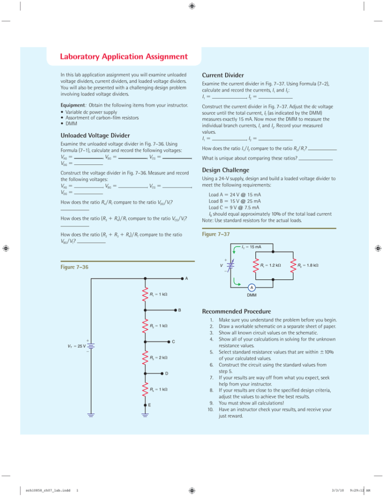
Laboratory Application Assignment In this lab application assignment you will examine unloaded voltage dividers, current dividers, and loaded voltage dividers. You will also be presented with a challenging design problem involving loaded voltage dividers. Current Divider Equipment: Obtain the following items from your instructor. • Variable dc power supply • Assortment of carbon-film resistors • DMM Construct the current divider in Fig. 7–37. Adjust the dc voltage source until the total current, IT (as indicated by the DMM) measures exactly 15 mA. Now move the DMM to measure the individual branch currents, I1 and I2. Record your measured values. I1 ⫽ , I2 ⫽ Examine the current divider in Fig. 7–37. Using Formula (7–2), calculate and record the currents, I1 and I2: I1 ⫽ , I2 ⫽ Unloaded Voltage Divider Examine the unloaded voltage divider in Fig. 7–36. Using Formula (7–1), calculate and record the following voltages: VAG ⫽ , VBG ⫽ , VCG ⫽ VDG ⫽ How does the ratio I1兾I2 compare to the ratio R2兾R1? , Construct the voltage divider in Fig. 7–36. Measure and record the following voltages: VAG ⫽ , VBG ⫽ , VCG ⫽ , VDG ⫽ How does the ratio R4兾RT compare to the ratio VDG兾VT? How does the ratio (R3 ⫹ R4)兾RT compare to the ratio VCG兾VT? How does the ratio (R2 ⫹ R3 ⫹ R4)兾RT compare to the ratio VBG兾VT? What is unique about comparing these ratios? Design Challenge Using a 24-V supply, design and build a loaded voltage divider to meet the following requirements: Load A ⫽ 24 V @ 15 mA Load B ⫽ 15 V @ 25 mA Load C ⫽ 9 V @ 7.5 mA IB should equal approximately 10% of the total load current Note: Use standard resistors for the actual loads. Figure 7–37 I T 15 mA R1 1.2 k V Figure 7–36 R2 1.8 k A A R1 1 k DMM B R2 1 k C V T 25 V Recommended Procedure 1. 2. 3. 4. 5. R3 2 k 6. D R4 1 k E sch10858_ch07_lab.indd 1 7. 8. 9. 10. Make sure you understand the problem before you begin. Draw a workable schematic on a separate sheet of paper. Show all known circuit values on the schematic. Show all of your calculations in solving for the unknown resistance values. Select standard resistance values that are within ⫾10% of your calculated values. Construct the circuit using the standard values from step 5. If your results are way off from what you expect, seek help from your instructor. If your results are close to the specified design criteria, adjust the values to achieve the best results. You must show all calculations! Have an instructor check your results, and receive your just reward. 3/3/10 9:29:12 AM


