dc high-voltage divider evaluation using the binary step-up
advertisement

XX IMEKO World Congress
Metrology for Green Growth
September 9-14, 2012, Busan, Republic of Korea
DC HIGH-VOLTAGE DIVIDER EVALUATION USING THE BINARY STEP-UP
METHOD
Sang Hwa Lee, Kwang Min Yu, Jeon Hong Kang and *Seok Myeong Jang
Korea Research Institute of Standards and Science (KRISS), *Chung-Nam National University
shlee@kriss.re.kr
Abstract: An evaluation technique and traceability for a
DC-resistive high-voltage divider was established based on
1 kV, which was traceable to a Josephson voltage standard
at the Korea Research Institute of Standards and Science. To
do this, the binary step-up method was used to evaluate the
voltage-dividing ratio and the voltage coefficient of the
divider up to 100 kV. The expanded relative uncertainty for
the dividing ratio up to 100 kV was 16 ´ 10–6 level. To
confirm the validity of the method, the ratio at 1 kV was
compared with the resistance ratio of the divider, and the
two results agreed to within 5.3 ´ 10–6.
Keywords: Josephson voltage standard, Binary step-up,
DC high-voltage ratio, DC-resistive high-voltage divider,
voltage coefficient.
1. INTRODUCTION
The most common method used to evaluate the
dividing ratio is to measure the resistance on the highvoltage and low-voltage arms of the divider [1]. However,
our goal was to establish a traceability that would be based
on a national voltage standard, the Josephson voltage
standard, and to use a technique to evaluate the dividing
ratio precisely using the binary step-up method. In this paper,
we present our results of our experiments for accurately
determining the voltage coefficient and voltage-dividing
ratio, as well as discussing the effect of temperature on the
DC high-voltage dividers up to 100 kV using the method.
2. MEASUREMENT METHOD AND APPARATUS
To determine the voltage-dividing ratio and voltage
co efficient of a high-voltage divider that is traceable to a
Josephson voltage standard using the binary step-up
method[2], two high-voltage resistors with the same
nominal value, R1 and R2, and a single voltage resistor, r, are
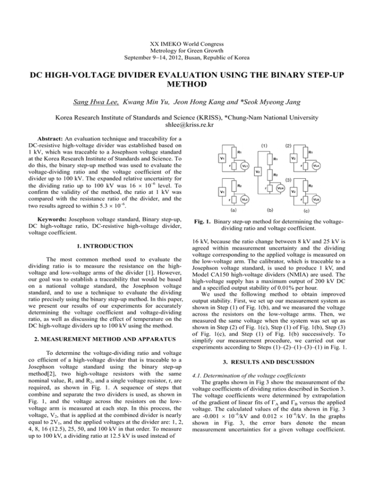
required, as shown in Fig. 1. A sequence of steps that
combine and separate the two dividers is used, as shown in
Fig. 1, and the voltage across the resistors on the lowvoltage arm is measured at each step. In this process, the
voltage, V2, that is applied at the combined divider is nearly
equal to 2V1, and the applied voltages at the divider are: 1, 2,
4, 8, 16 (12.5), 25, 50, and 100 kV in that order. To measure
up to 100 kV, a dividing ratio at 12.5 kV is used instead of
Fig. 1. Binary step-up method for determining the voltagedividing ratio and voltage coefficient.
16 kV, because the ratio change between 8 kV and 25 kV is
agreed within measurement uncertainty and the dividing
voltage corresponding to the applied voltage is measured on
the low-voltage arm. The calibrator, which is traceable to a
Josephson voltage standard, is used to produce 1 kV, and
Model CA150 high-voltage dividers (NMIA) are used. The
high-voltage supply has a maximum output of 200 kV DC
and a specified output stability of 0.01% per hour.
We used the following method to obtain improved
output stability. First, we set up our measurement system as
shown in Step (1) of Fig. 1(b), and we measured the voltage
across the resistors on the low-voltage arms. Then, we
measured the same voltage when the system was set up as
shown in Step (2) of Fig. 1(c), Step (1) of Fig. 1(b), Step (3)
of Fig. 1(c), and Step (1) of Fig. 1(b) successively. To
simplify our measurement procedure, we carried out our
experiments according to Steps (1)–(2)–(1)–(3)–(1) in Fig. 1.
3. RESULTS AND DISCUSSION
4.1. Determination of the voltage coefficients
The graphs shown in Fig 3 show the measurement of the
voltage coefficients of dividing ratios described in Section 3.
The voltage coefficients were determined by extrapolation
of the gradient of linear fits of GA and GB versus the applied
voltage. The calculated values of the data shown in Fig. 3
are -0.001 ´ 10–6/kV and 0.012 ´ 10–6/kV. In the graphs
shown in Fig. 3, the error bars denote the mean
measurement uncertainties for a given voltage coefficient.
The uncertainties of GA and GB shown in Fig. 3 are 4.19 ´
10–6 and 3.67 ´ 10–6, respectively.
Voltage coefficient of the high-voltage divider:
- Mean standard deviation of GA, GB
- Error from the gradient of linear fits of GA, GB
- Standard deviation of linear fits of GA, GB
GA
3.91 ´ 10-6,
0.016 ´ 10-6,
1.50 ´ 10-6,
GB
2.79 ´ 10-6
0.026 ´ 10-6
2.38 ´ 10-6
Combined standard uncertainty (voltage coeff.)
4.19 ´ 10-6,
3.67 ´ 10-6
Effect of temperature on the dividing ratio
1.15 ´ 10-6
Stability of the high-voltage supply
4.54 ´ 10-6
8.05 ´ 10-6,
7.79 ´ 10-6
16.10 ´ 10-6,
15.58 ´ 10-6
Combined standard uncertainty. divider A, divider B
Expanded uncertainty. (k = 2, confidence level of
95 %)
(Note: The uncertainty of VL is taken from the range of 4
kV which has the largest uncertainty in the range from 1
kV to 100 kV)
(Offsets of +120 ´ 10–6 and -90 ´ 10–6 are applied to them,
respectively, to discriminate between GA and GB results)
5. CONCLUSIONS
Fig. 3. Voltage coefficients of the high-voltage dividers
determined using the binary step-up method.
The voltage-dividing ratio and voltage coefficient of
a DC high-voltage divider up to 100 kV were accurately
evaluated using a binary step-up method. The advantage of
this method is that it is always traceable to a national voltage
standard, the Josephson voltage standard, in contrast to
existing methods. The expanded uncertainty of these
dividers up to 100 kV was estimated to be 16 ´ 10–6 level.
To validate the method of using the dividing ratios given by
1 kV, which is a reference voltage, the results were
compared with the resistance ratios given by resistance
measurements on the high-voltage and low-voltage arms,
and it was confirmed that they agreed to within 5.3 ´ 10–6.
In addition, the stability of the high-voltage supply
improved from 0.01% per hour to 4.54 ´ 10–6 up to 100 kV.
The largest factors influencing the uncertainty were
considered to be the uncertainty in the calibration in the DC
200 mV range of the DMM and the stability of the highvoltage supply. However, it is expected that these factors can
be improved on using a direct calibration from a
programmable Josephson voltage standard, which is under
development, and by using a more stable high-voltage
supply.
In the graphs shown in Fig. 3, the error bars denote the
mean measurement uncertainties for a given voltage
coefficient. The uncertainties of GA and GB shown in Fig. 3
are 4.19 ´ 10–6 and 3.67 ´ 10–6, respectively.
4.2. Estimation of the uncertainty
The measurement model for determining the dividing
ratios is given as follows.
GA(V2)=V2/VLA=VLN(GA(V1) + GB(V1) – 1)/VLA
(1)
According to the Law of Propagation of Uncertainty in the
ISO GUM Guide [4], the relative combined standard
uncertainty for the model is given in a linear approximation
by
u2{GA(V2)}/{GA(V2)}2≒u2(VLA)/(VLA)2+(VLN)/(VLN)2+
1/4´u2(V1)/(V1)2+1/4´u2(VL1)/(VL1)2+1/4´u2(V1)/(V1)2+
1/4´u2(VL2)/(VL2)2+1/2´u2(V1)/(V1)2
(2)
The first two terms and the last two terms mean the
uncertainties for the DMM measurements and the other two
terms mean the calibration uncertainties for the applied
voltage. The parameters represented in equation (2)
correspond to Figure 1 and the estimated uncertainty at the
previous step influences on the uncertainty at the next step.
Therefore, the DMM uncertainties for all steps were
estimated based on equation (2) and among them, the DMM
uncertainty in the range of 4 kV which has the largest
uncertainty was shown in Table 1.
Table 1 Uncertainty budget for the voltage-dividing ratio
measurements using the binary step-up method.
Uncertainty components
VL (1 kV ~ 100 kV, A) and VL (1 kV ~ 100 kV, B)
uncertainty:
-Type A Uncertainty of the VL (4 kV)
-Calibration and stability(24 hours) of the DMM(200
mV ~ 20 V range) and the meter calibrator @ 1 kV
(estimated by equation (12))
Standard uncertainty
1.13 ´ 10-6
4.90 ´ 10-6
6. REFERENCES
[1] J. H. Park, Special Shielded Resistor for High-Voltage
DC Measurements, JOURNAL OF RESEARCH of the
National Bureau of Standards-C, Engineering and
Instrumentation, Vol. 66C, No. 1, January-March 1962
[2] Kyu Tae Kim, Sang Hwa Lee, Jae Kap Jung, Yang Sup
Song, Method to Determine the Voltage Coefficient of a DC
High-Voltage
Divider,
IEEE
Transactions
On
Instrumentation and Measurement, vol. 53, No. 2, April
2003.
[3] Yi Li, Development of Precision DC High Voltage
Dividers, 2010 Conference on Precision Electromagnetic
Measurements, 13-18, June 2010
[4] ISO/IEC GUIDE 98-3:2008(E), Guide to the expression
of uncertainty in measurement (GUM:1995)


