TECK 90 SPECIFICATIONS
CSA TECK 90 5000V NON-SHIELDED EPR POWER CABLE
PRODUCT HIGHLIGHTS
Southwire’s 5KV TECK 90, 5000V, non-shielded, EPR insulated power cable is a CSA approved armoured cable for industrial and commercial medium voltage applications. FT4, -40C,
HL, AG14 and 90°C rated for use in harsh Canadian environments. Rated for installation in cable trays, duct banks, direct burial, troughs, hazardous locations, continuous rigid cable supports, and is
concrete encaseable.
CONSTRUCTION
Conductor
• Class B stranded copper
- compressed or compact
- in accordance with ASTM B3 and ASTM B8
• Optional Class B compact stranded 8000 Series Aluminum ACM
Conductor Shield
• Extruded semi-conducting thermosetting polymeric layer
Grounding Conductor
Armour
Fillers
Overall Jacket
• Class B compressed or compact stranded bare copper
- in accordance with ASTM B3 and B8
• Aluminum Interlocked Armour (AIA)
• Optional Galvanized Steel Interlocked Armour (GSIA)
• Non-wicking, non-hygroscopic
• Orange PVC (optional colours available)
• Thickness:
- No. 2 AWG to 250 kcmil = 0.060” (1.5 mm)
- 350 kcmil to 750 kcmil = 0.075” (1.9 mm)
- 1000 kcmil = 0.090” (2.3 mm)
Inner Jacket
• Black PVC
• Thickness:
- No. 2 AWG to No. 3/0 AWG = 0.080” (2.0 mm)
- No. 4/0 AWG to 500 kcmil = 0.110” (2.8 mm)
- 750 kcmil to 1000 kcmil = 0.140” (3.6 mm)
Insulation
• No-Lead EPR (ethylene propylene rubber)
• Thickness: 0.090” (2.3 mm) - nominal
• 90°C rated
Print Legend
• SOUTHWIRE [symbol - lightning bolt] #P# CSA LL90458 3/C
[AWG 2 to 1000 kcmil] CU TECK 90 EPR CDRS WITH GROUND -40°C
FT4 SUN. RES. AG14 5000V HL YEAR SEQUENTIAL METER MARKS
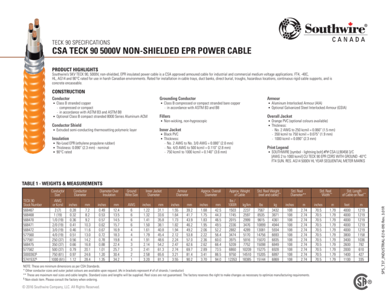
TABLE 1 - WEIGHTS & MEASUREMENTS
Conductor
Diameter
inches
0.28
0.32
0.36
0.41
0.46
0.51
0.56
0.66
0.79
0.97
1.12
mm
7.2
8.2
9.2
10.3
11.6
13.0
14.2
16.8
20.1
24.6
28.4
Diameter Over
Insulation
inches
0.49
0.53
0.57
0.62
0.67
0.72
0.78
0.88
1.01
1.20
1.35
mm
12.4
13.5
14.5
15.7
16.9
18.3
19.8
22.4
25.7
30.4
34.2
Ground
Wire Size
AWG
6
6
6
6
4
4
4
3
3
2
1
Inner Jacket
Diameter
inches
1.22
1.32
1.41
1.50
1.61
1.79
1.91
2.14
2.41
2.58
3.20
mm
31.1
33.6
35.8
38.1
40.8
45.4
48.6
54.2
61.3
65.6
81.3
Armour
Diameter
inches
1.55
1.64
1.73
1.82
1.94
2.12
2.24
2.47
2.74
3.21
3.55
mm
39.2
41.7
43.9
46.2
49.2
53.8
57.0
62.6
69.7
81.4
90.2
Approx. Overall
Diameter
inches
1.68
1.75
1.83
1.95
2.06
2.22
2.36
2.62
2.89
3.41
3.70
mm
42.5
44.3
46.5
49.5
52.2
56.4
60.0
66.4
73.5
86.5
94.0
Approx. Weight
of Cable
lbs /
1000ft
kg/km
1503
2237
1745
2597
2015
2999
2336
3476
2882
4289
3474
5170
3975
5916
5209
7752
6860
10209
9750
14510
12353 18385
Std. Reel Weight
(reel and cable)**
lbs
7567
8535
9615
10899
13081
14756
15070
15098
15275
15205
15144
kg
3432
3871
4361
4944
5934
6693
6835
6849
6928
6897
6869
Std. Reel
Diameter**
inches
108
108
108
108
108
108
108
108
108
108
108
m
2.74
2.74
2.74
2.74
2.74
2.74
2.74
2.74
2.74
2.74
2.74
NOTE: These are minimum dimensions as per CSA Standards.
* Other conductor sizes and outer jacket colours are available upon request. (#s in brackets represent # of of strands / conductor)
** These are maximum reel sizes and cable lengths. Standard sizes and lengths will be supplied. Reel sizes are not guaranteed. The factory reserves the right to make changes as necessary to optimize manufacturing requirements.
§ Non-stock item. Please consult the factory when ordering.
© 2016 Southwire Company, LLC. All Rights Reserved.
Std. Reel
Width**
inches
70.5
70.5
70.5
70.5
70.5
70.5
70.5
70.5
70.5
70.5
70.5
m
1.79
1.79
1.79
1.79
1.79
1.79
1.79
1.79
1.79
1.79
1.79
Std. Length
of Cable on Reel**
feet
4000
4000
4000
4000
4000
3800
3400
2600
2000
1400
1100
m
1219
1219
1219
1219
1219
1158
1036
792
610
427
335
SPS_T37_INDUSTRIAL-E(16-09) Rev. 3.01R
TECK 90
Stock Number
568467
568468
568470
568471
568472
577560
577561
568475
577562
S000363§
S741532§
Conductor
Size*
AWG
or Kcmil
2 (7)
1 (19)
1/0 (19)
2/0 (19)
3/0 (19)
4/0 (19)
250 (37)
350 (37)
500 (37)
750 (61)
1000 (61)
TECK 90 SPECIFICATIONS
CSA TECK 90 5000V NON-SHIELDED EPR POWER CABLE
DESIGN
Qualification Standards
•
•
•
•
CSA C22.2 No. 131 - Type TECK 90 Cable
CSA C22.2 No. 174 - Cables in Hazardous Locations
CSA C22.2 No. 2556 & No. 0.3. - Wire and Cable Test Methods
ICEA S-96-659 (NEMA WC71) - Nonshielded Cables Rated
2001-5000 Volts
Flame Test Ratings
•
•
•
•
FT1 - Flame Test (1,706 BTU/Hr nominal - Vertical Wire Flame Test)
FT4 - Flame Test (70,000 BTU/Hr - Vertical Tray Flame Test)
IEEE 383 - Flame Test (70,000 BTU/Hr)
IEEE 1202 - Flame Test (70,000 BTU/Hr - Vertical Tray Test)
Product Ratings
• CSA C22.2 No. 2556 & No. 0.3. - Wire and Cable Test Methods
• CSA LTGG [-40°C] - as per C68.10 - for Cold Bend and Impact
•
•
•
•
rating
CSA HL - for Hazardous Locations rating
CSA FT4 - for Flame Retardancy rating
CSA SUN RES - for Sunlight Resistant rating
CSA AG14 - for Acid Gas Compliance
COPPER CONDUCTOR
Operating Temperatures
• -40°C - CSA Cold Bend and Impact Temperature
• -25°C - Min. Installation Temperature
• 90°C - Max. Continuous Operating Temperature
CONDUCTOR SHIELD
INSULATION
GROUND CONDUCTOR
POLY TAPE
FILLER
INNER PVC JACKET
ALUMINUM INTERLOCK ARMOUR
End View
OVERALL PVC JACKET
TECK 90
Stock Number
568467
568468
568470
568471
568472
577560
577561
568475
577562
S000363§
S741532§
Conductor
Size*
AWG
or Kcmil
2 (7)
1 (19)
1/0 (19)
2/0 (19)
3/0 (19)
4/0 (19)
250 (37)
350 (37)
500 (37)
750 (61)
1000 (61)
Minimum
Bend Radius
inches
11.7
12.2
12.8
13.6
14.4
15.5
16.5
18.3
20.3
23.8
25.9
mm
298
310
326
346
366
395
420
465
514
605
658
DC Resistance
Maximum
@ 25°C
Pulling Tension
RDC
Ω/
Ω/
lbs Newtons 1000 ft.
km
1593
7084 0.1620 0.5315
2009
8935 0.1290 0.4232
2534 11274 0.1020 0.3347
3194 14209 0.0810 0.2658
4027 17914 0.0642 0.2106
5078 22590 0.0510 0.1673
6000 26689 0.0431 0.1414
8400 37365 0.0308 0.1011
12000 53379 0.0216 0.0709
18000 80068 0.0144 0.0472
24000 106757 0.0108 0.0354
AC Resistance
Ratios @ 90°C
& 60 Hz (each
conductor) RAC
Ω/
Ω/
1000 ft.
km
0.2180 0.7153
0.1730 0.5676
0.1340 0.4397
0.1070 0.3511
0.0850 0.2789
0.0680 0.2231
0.0570 0.1870
0.0410 0.1345
0.0290 0.0951
0.0200 0.0656
0.0155 0.0509
* Other conductor sizes and outer jacket colours are available upon request.
† Ampacities are based on Table 2 of the 2012 Canadian Electrical Code Part I (30°C Ambient Temperature)
‡ Ampacities are based on Table D12A and Detail 1 of Diagram B4-3 of the 2012 Canadian Electrical Code Part I
§ Non-stock item. Please consult the factory when ordering.
© 2016 Southwire Company, LLC. All Rights Reserved.
Inductance
L
mH /
mH /
1000 ft
km
0.0907 0.2975
0.0882 0.2893
0.0855 0.2804
0.0832 0.2731
0.0807 0.2647
0.0785 0.2576
0.0778 0.2554
0.0751 0.2463
0.0725 0.2380
0.0706 0.2315
0.0690 0.2263
Capacitance (each
phase conducor)
C
μF
μF /
/ 1000 ft km
0.0905 0.2971
0.0979 0.3212
0.1074 0.3525
0.1167 0.3830
0.1297 0.4257
0.1430 0.4692
0.1479 0.4852
0.1711 0.5613
0.2000 0.6564
0.2305 0.7564
0.2625 0.8612
Inductive
Reactance @ 60Hz
XL
Ω/
Ω/
1000 ft.
km
0.0342 0.112
0.0332 0.109
0.0322 0.106
0.0314 0.103
0.0304 0.100
0.0296 0.097
0.0293 0.096
0.0283 0.093
0.0273 0.090
0.0266 0.087
0.0260 0.085
Capacitive
Capacitive
Short Circuit
Allowable
Allowable
Reactance @
Susceptance @
Current (each Ampacities in Ampacities
60Hz (phase to
60Hz (phase to phase conductor) Raceway Directly Buried
neutral) XC
neutral) BC
@ 60Hz
or Cable†
in Earth‡
MΩ • MΩ • μSiemens μSiemens
kAmps
Amps
Amps
1000ft
km
/1000ft /km
0.0293 0.0089 34.13 111.99
4.8
130
~
0.0271 0.0083 36.90 121.07
5.9
145
~
0.0247 0.0075 40.50 132.87
6.3
170
243
0.0227 0.0069 44.01 144.40
10.0
195
274
0.0204 0.0062 48.91 160.48
12.5
225
311
0.0186 0.0057 53.91 176.87
14.0
260
360
0.0179 0.0055 55.74 182.90
18.0
290
383
0.0155 0.0047 64.49 211.59
25.0
350
470
0.0133 0.0040 75.42 247.44
36.0
430
548
0.0115 0.0035 86.91 285.16
51.0
535
667
0.0101 0.0031 98.96 324.67
70.0
615
758
SPS_T37_INDUSTRIAL-E(16-09) Rev. 3.01R
TABLE 2 - ENGINEERING SPECIFICATIONS


