ADCP-80-512 • Issue 2 • September 1999
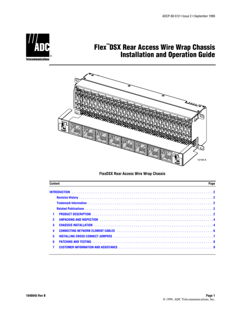
Flex™DSX Rear Access Wire Wrap Chassis
Installation and Operation Guide
12109-A
FlexDSX Rear Access Wire Wrap Chassis
Content
Page
INTRODUCTION ........................................................................... 2
Revision History ....................................................................... 2
Trademark Information .................................................................. 2
Related Publications .................................................................... 2
1040845 Rev B
1
PRODUCT DESCRIPTION ................................................................ 2
2
UNPACKING AND INSPECTION ............................................................ 4
3
CHASSSIS INSTALLATION ............................................................... 4
4
CONNECTING NETWORK ELEMENT CABLES ................................................... 6
5
INSTALLING CROSS-CONNECT JUMPERS ..................................................... 7
6
PATCHING AND TESTING ................................................................ 8
7
CUSTOMER INFORMATION AND ASSISTANCE .................................................. 9
Page 1
© 1999, ADC Telecommunications, Inc.
ADCP-80-512 • Issue 2 • September 1999
INTRODUCTION
This manual describes the ADC FlexDSX Rear Access Wire Wrap Chassis, and provides
procedures for unpacking, installing, and operating this product.
Revision History
ISSUE
DATE
REASON FOR CHANGE
Issue 1
01/99
Original.
Issue 2
09/99
Revised to add electrical ratings and warning. Product name change.
Trademark Information
ADC and ADC Telecommunications are registered trademarks of ADC Telecommunications, Inc.
FlexDSX is a trademark of ADC Telecommunications, Inc.
Related Publications
Title
1
ADCP Number
FlexDSX System Planning and Application Guide
80-511
DSX-1 Operational Procedures
80-514
PRODUCT DESCRIPTION
The FlexDSX Rear Access Wire Wrap Chassis is an individual frame module for the
FlexDSX Front Cross-Connect System. Figure 1 shows the front of the chassis, with its wirewrap field for cross-connect termination and bantam jack field for test, patch, and monitor
access.
As shown, the chassis has a horizontal wire way for cross-connect wires and a hinged front
door with a label for recording cross-connect terminations. The chassis is 132.1 mm (5.2 in.)
high, 482.6 mm (19.0 inches) wide, and 149.9 mm (5.9 inches) deep.
The chassis requires a connection of 48 volts DC nominal at 1.0 amps maximum to provide
power for the cross-connect tracer lamps located on each circuit module. When a patch cord is
inserted in the MON OUT port on one of a cross-connect circuit, the tracer lamps on both
ends of the circuit blink off and on.
Figure 2 shows the chassis rear with its wire wrap terminals for Network Element (NE)
terminations. Each chassis provides test and patch access for 64 NE terminations.
Page 2
© 1999, ADC Telecommunications, Inc.
ADCP-80-512 • Issue 2 • September 1999
BANTAM JACK FIELD
(TEST, PATCH, AND
MONITOR ACCESS)
MOUNTING TAB
(FOUR PLACES)
CIRCUIT POSITION 1
(64 POSITIONS PER CHASSIS)
HORIZONTAL
WIRE WAY FOR
CROSS-CONNECT
WIRES
DOOR LATCH
(TWO PLACES)
HINGED FRONT DOOR
WITH LABEL
WIRE-WRAP
CROSS-CONNECT
TERMINATION FIELD
12110-A
Figure 1. FlexDSX Chassis Main Components (Front View)
48V
48V RET
SHIELD
GND
48V BATTERY
TERMINAL BLOCK
EQUIPMENT FIELD (WIRE WRAP
PINS SHOWN FOR REFERENCE.
A VARIETY OF EQUIPMENT
FIELD TYPES ARE AVAILABLE). CIRCUIT MODULES ARE
AUTOMATICALLY POWERED
WHEN PLUGGED INTO CHASSIS
ONE CIRCUIT MODULE
BACKPLANE.
(16 PER CHASSIS)
CHASSIS
GROUND LUG
12111-A
Figure 2. FlexDSX Rear Access Wire Wrap Chassis (Rear)
Page 3
© 1999, ADC Telecommunications, Inc.
ADCP-80-512 • Issue 2 • September 1999
Figure 3 shows an individual circuit for even position jack card. For odd position jack card,
refer to ADCP-80-511, “FlexDSX System Planning and Application Guide.”
EVEN JACK CARD
JACK MOUNT AND REAR INTERFACE ASSEMBLY
-48V
-48V
TL
TL
RET
RET
R
R
TRACER
LAMP
MON OUT
F
R
O
N
T
OUT
IN
T
T
SG
SG
RO
RO
XRO
XRO
XTO
XTO
TO
TO
TI
TI
XTI
XTI
XRI
XRI
RI
RI
MON IN
T
T
R
R
TL
T
CROSS
CONNECT
OUT
R
IN
T
R
-48V
RET POWER
SG
R
E
A
R
T
OUT
R
EQUIPMENT
T IN
R
12112-A
Figure 3. FlexDSX Rear Access Wire Wrap Circuit Diagram
2
UNPACKING AND INSPECTION
Unpack the FlexDSX chassis carefully, checking it for damage. If any item is damaged, file a
claim with the commercial carrier and consult ADC Customer Service. Keep the damaged
shipping containers for use in the claim. Even though no damage is evident, save the shipping
container for use if the equipment requires shipment at a future date.
3
CHASSIS INSTALLATION
Warning: FlexDSX products are designed to be located in a dedicated restricted access
communication equipment area. Never install equipment in a wet location or during a
lightning storm. When installing or modifying telephone lines, disconnect lines at the network
interface before working with uninsulated wires or terminals.
1. Determine where the chassis will be placed on the rack. Refer to Figure 4 for correct
chassis position.
Page 4
© 1999, ADC Telecommunications, Inc.
ADCP-80-512 • Issue 2 • September 1999
45
UPPER HORIZONTAL
TROUGH
FUSE PANEL
40
CHASSIS POSITION 12
35
CHASSIS POSITION 11
CHASSIS POSITION 10
HOLE SPACINGS
AT INTERVALS OF
44.6 MM (1.75 IN)
30
CHASSIS POSITION 9
CHASSIS POSITION 8
25
2200 MM
(86.61 IN.)
CHASSIS POSITION 7
20
CHASSIS POSITION 6
CHASSIS POSITIONS
1 THOUGH 12
IN OVERHEAD CABLING ENVIRONMENT,
PLACE FIRST CHASSIS IN POSITION 12
AND SUBSEQUENT CHASSIS
IN POSITIONS 11, 10, 9, ETC.,
WORKING DOWNWARD.
IN RAISED FLOOR CABLING ENVIRONMENT,
PLACE FIRST CHASSIS IN POSITION 1
AND SUBSEQUENT CHASSIS
IN POSITIONS 2, 3, 4, ETC.,
WORKING UPWARD.
CHASSIS POSITION 5
15
CHASSIS POSITION 4
CHASSIS POSITION 3
10
CHASSIS POSITION 2
5
CHASSIS POSITION 1
LOWER HORIZONTAL
TROUGH
102.6 MM
(4.04 IN.)
12113-A
464.3 MM
(18.28 IN.)
MINIMUM OPENING
Figure 4. FlexDSX Chassis Positions
2. Align the top and bottom mounting tabs on each side of the chassis with the slotted holes
in the vertical cable guide, as shown in Figure 5. (Cable rings do not have to be
removed.) Fasten the chassis to the bay using two #12-24 - 0.375 inch (9.5 mm) machine
screws on each side of the chassis.
Page 5
© 1999, ADC Telecommunications, Inc.
ADCP-80-512 • Issue 2 • September 1999
3. Ground the chassis per local practice. A ground lug is available on the rear of the chassis
(refer to Figure 2 to identify the ground lug).
VERTICAL CABLE
GUIDE
MOUNTING TAB
RACK HOLE SPACINGS
AT INTERVALS OF
44.6 MM (1.75 IN.)
CHASSIS
ALIGN TOP AND BOTTOM
MOUNTING TABS
WITH SLOTTED HOLES
IN VERTICAL CABLE GUIDES.
FRONT VIEW
12114-A
Figure 5. Installing the Chassis
4. Connect the 48V Terminal Block on the rear of the chassis to the respective circuit on
the fuse panel as indicated in Figure 6. Also, check to ensure that the dummy fuses have
been removed from the fuse panel and replaced with the correct type fuses (0.5 GMT).
-48V (RED)
.
TO FIRST CHASSIS INSTALLED
(ON TOP OR BOTTOM OF RACK)
.
48V RET (BLACK)
SHIELD
GND
FUSE PANEL
TO SUBSEQUENT CHASSIS
TERMINAL BLOCK
(LEFT TO RIGHT
IN THE ORDER INSTALLED)
ROUTE ALONG RACK
THROUGH POWER WIRE
GUIDE/RETAINERS;
REFER TO SYSTEM MANUAL.
12115-A
CHASSIS 48V BATTERY
TERMINAL BLOCK
Figure 6. Connecting the Chassis to the Fuse Panel
4
CONNECTING NETWORK ELEMENT CABLES
1. Route the network element transmit and receive cables to the chassis following
instructions in ADCP-80-511, “FlexDSX System Planning and Application Guide.”
2. Prepare the individual wires to be terminated on the chassis by clipping off the ends
cleanly and stripping back the insulation about 4 cm (1.6 in.).
3. Terminate each transmit/receive (OUT/IN) circuit as follows:
Page 6
© 1999, ADC Telecommunications, Inc.
ADCP-80-512 • Issue 2 • September 1999
a.
b.
c.
d.
Identify the chassis pins to be used for termination. Figure 7 shows the Tip Out
(TO), Ring Out (RO), Tip In (TI), and Ring In (RI) pins for one NE termination.
Label the twisted pair for the network element transmit signal and route the wires to
the upper pins identified TO and RO.
Label the twisted pair for the network element receive signal and route the wires to
the lower pins identified TI and RI.
Connect each individual wire to the pin. ADC recommends using five stripped turns
plus one turn with insulation on three corners of the wire wrap pin (see Figure 7).
INSULATION
(ONE TURN ON
THREE CORNERS OF PIN)
STRIPPED WIRE
(FIVE TURNS)
RECOMMENDED
WIRE WRAP (ONE PIN)
TO
RO
TI
RI
REAR VIEW
WIRE WRAP
EQUIPMENT TERMINATION
FIELD (SHADED AREA
SHOWS PIN DESIGNATIONS
FOR CIRCUIT ONE)
12116-A
Figure 7. Termination Pins for One Network Element
Transmit/Receive (OUT/IN) Circuit
5
INSTALLING CROSS-CONNECT JUMPERS
To cross-connect between circuit modules for two network elements, use the wire-wrap pins
on the bottom front of the chassis, identified in Figure 8. Between the two circuit modules,
cross-connect the IN and OUT wires, as shown in Figure 9.
Page 7
© 1999, ADC Telecommunications, Inc.
ADCP-80-512 • Issue 2 • September 1999
LED
MONITOR OUT
OUT
PATCH AND TEST
JACK FIELD
IN
MONITOR IN
SHADED AREA IDENTIFIES
ONE CIRCUIT
TRACER LAMP
TO
WIRE WRAP
CROSS-CONNECT
FIELD
RO
TI
RI
FRONT VIEW
12117-A
Figure 8. Cross-Connect Wire Wrap Field
and Patch and Test Jack Field
GREEN
TL
BLUE
TO
BLUE-WHITE OUT RO
ORANGE
ORANGE-WHITE
TWISTED PAIRS
5 CONDUCTOR
JUMPER WIRE
TL
TI
IN
TO
RI
RO
CROSS-CONNECT
TERMINAL BLOCKS
OUT
TI
RI
IN
11893-B
Figure 9. Cross-Connect Wire Routing
6
PATCHING AND TESTING
For patching and testing. use the patch and test jackfield identified above in Figure 8. Refer to
ADCP-80-514, “DSX-1 Operational Procedures,” for individual procedures such as in-service
and out-of-service patching.
Page 8
© 1999, ADC Telecommunications, Inc.
ADCP-80-512 • Issue 2 • September 1999
7
CUSTOMER INFORMATION AND ASSISTANCE
For customers wanting information on ADC products or help in using them, ADC offers the
services listed below. To obtain any of these services by telephone, first dial the central ADC
telephone number, then dial the extension provided below.
The central number for calls originating in the U.S.A. or Canada is 1-800-366-3891. For calls
originating outside the U.S.A. or Canada, dial country code “1” then dial 612-946-3000.
Sales Assistance
Extension 3000
• Quotation Proposals
• Ordering and Delivery
• General Product Information
Systems Integration
Extension 3000
•
•
•
•
•
•
•
Complete Solutions (from Concept to Installation)
Network Design and Integration Testing
System Turn-Up and Testing
Network Monitoring (Upstream or Downstream)
Power Monitoring and Remote Surveillance
Service/Maintenance Agreements
Systems Operation
BCG Technical Assistance Center
Extension 3475
E-Mail: technical@adc.com
•
•
•
•
•
•
Technical Information
System/Network Configuration
Product Specification and Application
Training (Product-Specific)
Installation and Operation Assistance
Troubleshooting and Repair
Product Return Department
Extension 3748
E-Mail: repair&return@adc.com
• ADC Return Authorization number and instructions
must be obtained before returning products.
Product information may also be obtained using the ADC web site at www.adc.com or by
writing ADC Telecommunications, Inc., P.O. Box 1101, Minneapolis, MN 55440-1101, U.S.A.
Contents herein are current as of the date of publication. ADC reserves the right to change the contents without prior notice. In
no event shall ADC be liable for any damages resulting from loss of data, loss of use, or loss of profits and ADC further
disclaims any and all liability for indirect, incidental, special, consequential or other similar damages. This disclaimer of
liability applies to all products, publications and services during and after the warranty period.
This publication may be verified at any time by contacting ADC’s Technical Assistance Center at 1-800-366-3891, extension
3475 (in U.S.A. or Canada) or 612-946-3000 (outside U.S.A. and Canada), or by writing to ADC Telecommunications, Inc.,
Attn: Technical Assistance Center, Mail Station #71, P.O. Box 1101, Minneapolis, MN 55440-1101, U.S.A.
© 1999, ADC Telecommunications, Inc.
All Rights Reserved
Printed in U.S.A.
Page 9


