How inrush current limiters can improve power supplies
advertisement
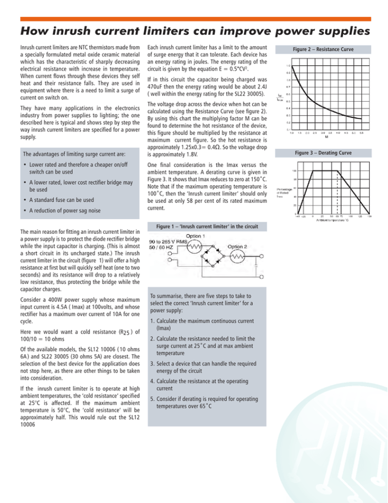
How inrush current limiters can improve power supplies Inrush current limiters are NTC thermistors made from a specially formulated metal oxide ceramic material which has the characteristic of sharply decreasing electrical resistance with increase in temperature. When current flows through these devices they self heat and their resistance falls. They are used in equipment where there is a need to limit a surge of current on switch on. They have many applications in the electronics industry from power supplies to lighting; the one described here is typical and shows step by step the way inrush current limiters are specified for a power supply. The advantages of limiting surge current are: • Lower rated and therefore a cheaper on/off switch can be used • A lower rated, lower cost rectifier bridge may be used • A standard fuse can be used • A reduction of power sag noise The main reason for fitting an inrush current limiter in a power supply is to protect the diode rectifier bridge while the input capacitor is charging. (This is almost a short circuit in its uncharged state.) The inrush current limiter in the circuit (figure 1) will offer a high resistance at first but will quickly self heat (one to two seconds) and its resistance will drop to a relatively low resistance, thus protecting the bridge while the capacitor charges. Consider a 400W power supply whose maximum input current is 4.5A ( Imax) at 100volts, and whose rectifier has a maximum over current of 10A for one cycle. Here we would want a cold resistance (R25 ) of 100/10 = 10 ohms Of the available models, the SL12 10006 ( 10 ohms 6A ) and SL22 30005 (30 ohms 5A) are closest. The selection of the best device for the application does not stop here, as there are other things to be taken into consideration. If the inrush current limiter is to operate at high ambient temperatures, the ‘cold resistance’ specified at 25°C is affected. If the maximum ambient temperature is 50°C, the ‘cold resistance’ will be approximately half. This would rule out the SL12 10006 Each inrush current limiter has a limit to the amount of surge energy that it can tolerate. Each device has an energy rating in joules. The energy rating of the circuit is given by the equation E = 0.5*CV2. Figure 2 – Resistance Curve If in this circuit the capacitor being charged was 470uF then the energy rating would be about 2.4J ( well within the energy rating for the SL22 30005). The voltage drop across the device when hot can be calculated using the Resistance Curve (see figure 2). By using this chart the multiplying factor M can be found to determine the hot resistance of the device, this figure should be multiplied by the resistance at maximum current figure. So the hot resistance is approximately 1.25x0.3= 0.4Ω. So the voltage drop is approximately 1.8V. One final consideration is the Imax versus the ambient temperature. A derating curve is given in Figure 3. It shows that Imax reduces to zero at 150˚C. Note that if the maximum operating temperature is 100˚C, then the ‘Inrush current limiter’ should only be used at only 58 per cent of its rated maximum current. Figure 1 – ‘Inrush current limiter’ in the circuit To summarise, there are five steps to take to select the correct ‘Inrush current limiter’ for a power supply: 1. Calculate the maximum continuous current (Imax) 2. Calculate the resistance needed to limit the surge current at 25˚C and at max ambient temperature 3. Select a device that can handle the required energy of the circuit 4. Calculate the resistance at the operating current 5. Consider if derating is required for operating temperatures over 65˚C Figure 3 – Derating Curve

