Application note for Inrush Current Limiters (ICL)
advertisement
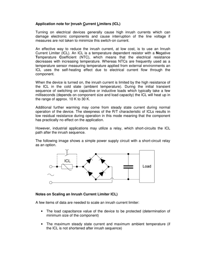
Application note for Inrush Current Limiters (ICL) Turning on electrical devices generally cause high inrush currents which can damage electronic components and cause interruption of the line voltage if measures are not taken to minimize this switch-on current. An effective way to reduce the inrush current, at low cost, is to use an Inrush Current Limiter (ICL). An ICL is a temperature dependent resistor with a Negative Temperature Coefficient (NTC), which means that the electrical resistance decreases with increasing temperature. Whereas NTCs are frequently used as a temperature sensor measuring temperature applied from external environments an ICL uses the self-heating effect due to electrical current flow through the component. When the device is turned on, the inrush current is limited by the high resistance of the ICL in the cold state (ambient temperature). During the initial transient sequence of switching on capacitive or inductive loads which typically take a few milliseconds (depends on component size and load capacity) the ICL will heat up in the range of approx. 10 K to 30 K. Additional further warming may come from steady state current during normal operation of the device. The steepness of the R/T characteristic of ICLs results in low residual resistance during operation in this mode meaning that the component has practically no effect on the application. However, industrial applications may utilize a relay, which short-circuits the ICL path after the inrush sequence. The following image shows a simple power supply circuit with a short-circuit relay as an option. Notes on Scaling an Inrush Current Limiter ICL) A few items of data are needed to scale an inrush current limiter: • The load capacitance value of the device to be protected (determination of minimum size of the component) • The maximum steady state current and maximum ambient temperature (if the ICL is not shortened after inrush sequence) • The required reduction of the inrush current (determination of the “cold resistance” at 25°C) • The maximum supply voltage Load Capacitance of Device to be Protected The high inrush current of devices results from the higher energy required to turn on. In power supplies the energy requirement is primarily caused by load capacitors, in transformers by magnetizing energy. The associated turn-on operation imposes a current pulse load on the inrush current limiter. So this energy must be known to select the right component. It can be converted into capacitance for a given voltage. This capacitance is used as a measure of the pulse handling capability (Ctest) of our inrush current limiters. Our Ctest figures refer to line voltages of 110 V and 230 V. If an inrush current limiter is operated at other voltages (e.g. the low voltages of electronic circuits), the appropriate Ctest figure is easily calculated: E= CV 2 2E ⇒C = 2 2 V The required Ctest determines the minimum size of the component. Steady-State Current and Maximum Ambient Temperature Select the component so that the steady-state current does not exceed the maximum admissible current (Imax) of the inrush current limiter. The maximum admissible current is produced from the figure for Imax and the derating with the maximum ambient temperature. When scaling a design, remember the possibility of line voltage fluctuations and different operating states (steady-state currents) of the device itself, and incorporate appropriate precautionary measures. The figure below shows the load derating curve for EPCOS ICLs. The following equations can be used to calculate the load derating according to the above mentioned curves. I max(65...170°C ) ( S153...S 464) = (− 0,0095 ⋅ T A + 1,62 ) ⋅ I max(0...65°C ) I max(25..170°C ) ( S 237) = (− 0,0069 ⋅ T A + 1,17 ) ⋅ I max(0...25°C ) Required Reduction of Inrush Current The required Ctest figure alone will determine the component that is needed. Within this component model the maximum steady-state current then determines the highest possible cold resistance (R25) that can be used for an application. The higher the cold resistance (R25) of the inrush current limiter, the more the inrush current is dampened. If the current limiting effect of a component is inadequate, choose a larger model. Scaling examples: ICL Types: R25 Ohm 1.0 2.0 2.5 4.0 5.0 10.0 Imax B25/100 (0…65°C) A K 16.0 2800 12.0 2900 11.0 2900 9.5 3060 8.5 3060 7.5 3300 Ctest 230V µF 1000 1200 1200 1550 1550 1550 Ctest 110V µF 4400 5250 5250 6800 6800 6800 Max Energy J 70 90 90 110 110 110 Ordering code B57364S2109A B57364S2209A B57364S2259A B57364S2409A B57364S2509A B57364S2100A 2 2 2 2 2 2 Capacitive Applications In this example a capacitor in a SMPS will be charged Load capacitance: Max. steady state current: Max. line voltage: 2500 µF 12.0 A at ambient temperature from 0°C to 45°C 110 Vac + 10% = 121 Vac From max. line voltage the max. peak voltage can be calculated by Vmax( peak ) = 121 ⋅ 2 = 171,1V Considerations and Calculations: Calculation of the maximum load capacitance for this series under the actual operating conditions gives: 110 2 = 3636 µF > 2500 µF 1212 (The lowest Cmax of this example series has been assumed.). Cmax = 4400 µF ⋅ The actual energy can be calculated as follows: E= CV 2 2500 µF .171.1² = = 36.6 J 2 2 Based upon the continuous current of 12A and a calculated energy rating of 36.3J the EPCOS types B57364S2109A 2 and B57364S2209A 2 would be suitable. If the ambient temperature had exceeded 65°C as given then derating on the Imax as per the following would need to be applied: Inductive Applications However, the use of ICLs is not limited to the reduction of inrush currents in power supplies. They are also ideal for the protection of transformers and the soft starting of motors (e.g. in power tools, compressors, vacuum cleaners, conveyor belts etc.) In the next example we will consider the inrush current reduction in a transformer. Transformer: Measured inrush current: Line voltage / tolerance: Frequency: Transformer efficiency: 1.0 KVA 350 A 110 Vac ± 10% = 99 / 121Vac 60Hz 70% Maximum steady state current can be calculated through the KVA rating, the efficiency rating and minimum line voltage: I= KVA 1000 = = 14.4 A efficiency.Min _ Voltage 0.70 * 99 To calculate the maximum energy, we need to take into consideration the in inrush current (ISC) and the Inductive Reactance (Z). We need to use the measured inrush current and the maximum supply voltage to determine the reactance of the transformer. 121V = 0.35Ω 350 A Form this we can determine the inductivity of the transformer using the formula: Hence, Z = 0.35 = 0.000928 H = 0.928µH 2 * π * f 2 * 3.142 * 60 Where f is the given supply frequency in Hertz. L= Z = Since energy equates to E = 0.5 * Z * I ² where I is the maximum inrush current, we can calculate that the Energy that must be absorbed by the ÎCL is E = 0.5 * 0.000928 H * 350 A² = 56.8.J Hence, a suitable ICL for this application would be the B57364S2109A 2 as this has a Joule rating of 70J and is specified with maximum steady state current from 0 to 65°C of 16.0A.
