LED Pendant Series
advertisement

LED Pendant Series
LED Pendant Light
Models: AT, BE, GE, KE, LA, & SX
Safety Precautions
Read all safety precautions and installation instructions carefully
before installing or servicing this fixture. Failure to comply with
these instructions could result in potentially fatal electric shock
and/or property damage.
It is recommended that a qualified electrician perform all wiring. This
fixture must be wired in accordance with all national and local
electrical codes.
Do not handle any energized fixture or attempt to energize any
fixture with wet hands or while standing on a wet or damp surface or
in water.
Assembly Instructions
1. Preparing for Installation -
Make sure that the power source conforms to the requirements of the
fixture. (See labels on fixture housing).
To reduce the risk of electrical shock, and to assure proper operation,
this fixture must be adequately grounded. To accomplish proper
grounding there must be a separate ground wire (green) or bare metal
contact (metal conduit) between this fixture and the ground
connection of your main power supply panel. The green ground
screw location is clearly marked on the fixture housing.
This fixture is intended to be used for general lighting in dry or damp
locations only.
A. Feed the black and white supply wires, and the green
B.
A. Disconnect electrical power before installing or servicing
any part of this fixture.
B. Remove light fixture, decorative hardware, isolation
C.
canopy and parts bag from carton
2. Fixture Assembly A. Uncoil coax cable (5) and thread loose end through strain
D.
relief (7) (smaller end toward Pendant fixture).
B. Temporarily secure strain relief onto coax cable at desired
height by tightening setscrew using hex-wrench provided.
C. Feed the decorative canopy (6) through coax cable.
D. Prepare the outer braided wire (-) and insulated conductor
(+) for wiring onto LED driver.
3. Fixture Mounting & Wiring Caution: Make sure power is off at fuse or circuit breaker box.
Check power wires for damage or scrapes. If power supply wires are
within three inches of ballast use wire suitable for at least 90C
(194F). Note: Most dwellings built before 1985 have supply wire
rated to 60C. Consult a qualified electrician before installing.
E.
F.
G.
H.
I.
J.
A.
ground wire into isolation canopy (1) through the off-center
hole.
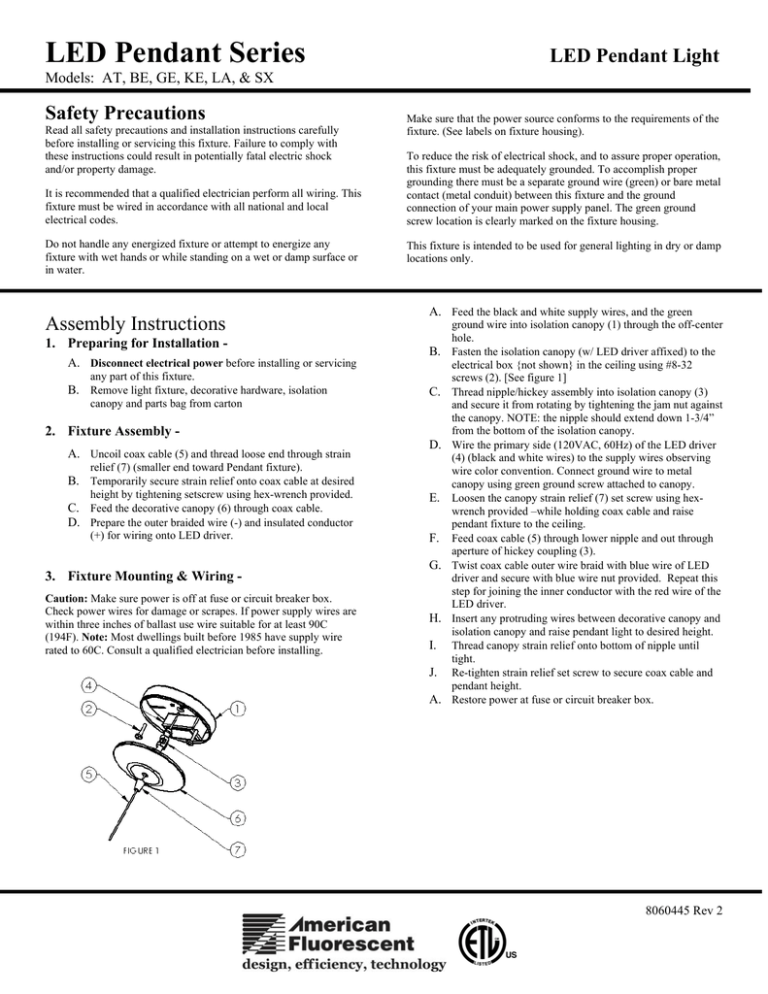
Fasten the isolation canopy (w/ LED driver affixed) to the
electrical box {not shown} in the ceiling using #8-32
screws (2). [See figure 1]
Thread nipple/hickey assembly into isolation canopy (3)
and secure it from rotating by tightening the jam nut against
the canopy. NOTE: the nipple should extend down 1-3/4”
from the bottom of the isolation canopy.
Wire the primary side (120VAC, 60Hz) of the LED driver
(4) (black and white wires) to the supply wires observing
wire color convention. Connect ground wire to metal
canopy using green ground screw attached to canopy.
Loosen the canopy strain relief (7) set screw using hexwrench provided –while holding coax cable and raise
pendant fixture to the ceiling.
Feed coax cable (5) through lower nipple and out through
aperture of hickey coupling (3).
Twist coax cable outer wire braid with blue wire of LED
driver and secure with blue wire nut provided. Repeat this
step for joining the inner conductor with the red wire of the
LED driver.
Insert any protruding wires between decorative canopy and
isolation canopy and raise pendant light to desired height.
Thread canopy strain relief onto bottom of nipple until
tight.
Re-tighten strain relief set screw to secure coax cable and
pendant height.
Restore power at fuse or circuit breaker box.
8060445 Rev 2
LED Pendant Series
LED Pendant Light
Models: AT, BE, GE, KE, LA, & SX
LED Replacement Instructions
NOTES:
Disconnect electrical power before servicing any part of this fixture.
Allow LED fixture to cool-down for 1 hour before attempting to replace
lamps.
A. Loosen strain relief (1) set screw and slide strain relief and
metal escutcheon (3) up coax cable (2).
B. Loosen jam nut (4) and slide nut, washer (5), and glass (6)
up coax cable in order to access LEDs (8).
C. Repeat the previous step for the plastic baffle (7) if present.
There are 5 LED’s in the fixture; 2 up-lights and 3 down-lights.
D. Unscrew LED’s (8) by turning counter clockwise until
detached from fixture. Discard old LED’s
E. Screw new LED’s into each threaded socket by turning
them clockwise until fully seated.
F. Restore electrical power to LED Pendant fixture.
LED Replacement parts –
RP-5005090
RP-5005091
RP-5005092
Glass Color
Blue
(Qty 1) Warm White LED, 1Watt; 2700K
(Qty 1) Cool White LED, 1Watt; 4000K
(Qty 1) Blue LED, 1Watt
LED Replacement Part No.
Up-lights (2)
RP-5005092
Down-lights (3)
RP-5005091
Amber
RP-5005090
Amber Stone
RP-5005090
Green
RP-5005091
Red
RP-5005091
White
RP-5005091
8060445 Rev 2


