Introduction to Microscopy
advertisement
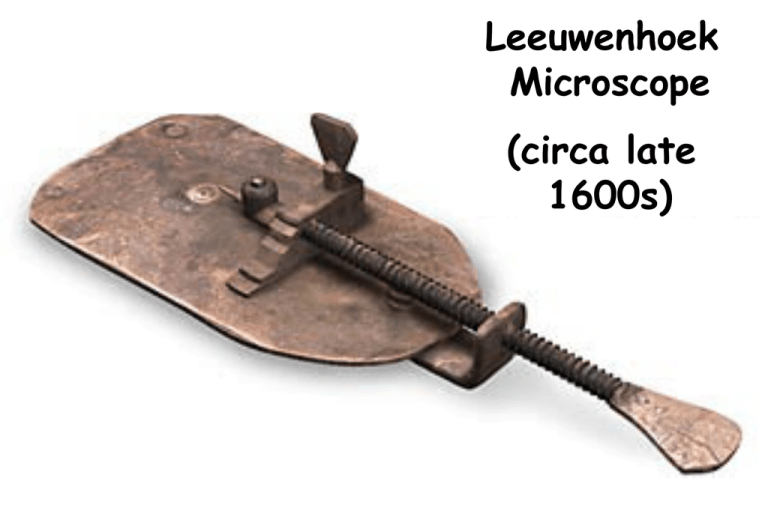
Leeuwenhoek The simple microscope Microscope (circa late 1600s) Transmitted and Fluorescence Illumination Upright microscope . Inverted microscope The Microscope’s Most Important Component The Objective http://www.microscopyu.com/articles/optics/objectiveintro.html http://zeiss-campus.magnet.fsu.edu The second most important component… The Condenser Condenser maximizes resolution dmin = 1.22 λ / (NA objective +NA condenser) Kohler Illumination: Condenser and objective focused at the same plane Resolution versus Contrast • d = 0.61λ/NA • λ=wavelength; NA=Numerical Apeture 0 Units 50 Units 100 Units C ONTRAST 50 Units 50 0 -0.33 1 50 – 50 / 50 + 50 = 50 – 0 / 50 + 0 = 50 – 100 / 50 + 100 = Brightness of Specimen - Brightness of Background Brightness of Specimen + Brightness of Background 50 Electromagnetic Spectrum Higher Resolution Longer Illumination Techniques - Overview Transmitted Light Incident Light • • • • • Darkfield • Polarized Light • Fluorescence (Epi) • Brightfield • Oblique Darkfield Phase Contrast Polarized Light DIC (Differential Interference Contrast) • Brightfield • Oblique DIC (Nomarski) " High Contrast and high resolution " Full Control of condenser aperture " 3-D Image appearance " Color DIC by adding a wave plate " Selectable contrast / resolution via different DIC sliders " Orientation-specific > orient fine details perpendicular to DIC prism DIC (Differential Interference Contrast) after Nomarski Observing local differences in phase retardation 9 Image 8 Tube lens 7 Analyzer (7a with Wave Plate) 6 Wollaston Prism behind objective 5 Objective 4 Specimen 3 Condenser 2 Wollaston Prism before condenser 1 Polarizer Required Components for DIC: • Nosepiece with DIC receptacles • Polarizer • Low Strain Condenser and Objective • DIC Prisms for Condenser (#I orII orIII) • Specific DIC Slider for each objective • Analyzer Fluorescence • Easy to set up > Objective = Condenser • Highly specific technique, wide selection of markers • Detection and Identification of Proteins, Bacteria, Viruses • Basics for – – – – – Special Techniques eg. TIRF, FRET, FRAP etc. 3-D imaging Deconvolution Structured Illumination Confocal Techniques Where does energy go? Green light emitted Blue light absorbed Quantum Yield = light out/light in 490nm Stokes Shift 520nm Q ~ 0.8 fluorescein ~ 0.3 rhodamine Light Sources • Mercury (Hg) • Xenon, Hg/Xe Combination • Laser • LED’s • Tungsten Halogen Epi - Fluorescence (Specimen containing green fluorescing Fluorochrome) Observation port Excitation Filter FL Light Source Specimen containing green fluorescing Fluorochrome Emission Filter Dichromatic Mirror How to improve Fluorescence Imaging in a major way: • Optical Sectioning Overview of Optical sectioning Methods 1. Confocal and Multi-photon Laser Scanning Microscopy – – Pinhole prevents out-of-focus light getting to the sensor(s) (PMT - Photomultiplier) Multi Photon does not require pinhole 2. Spinning disk systems – – A large number of pinholes (used for excitation and emission) is used to prevent out-of-focus light getting to the camera E.g. Perkin Elmer, Solamere 3. Deconvolution – – Point-Spread function (PSF) information is used to calculate light back to its origin Post processing of an image stack Laser Scanning Confocal Microscopes (LSCM) Zeiss LSM710 with Two-photon laser Chameleon Ultra II Laser Leica SP5 Spectral High Speed Confocal Microscopy just a form of Fluorescence Microscopy www.olympusfluoview.com Optical Sectioning: Increased Contrast and Sharpness. Examples: Zebrafish images, Inner ear • Bit Depth • 8 bits = 256 • 12 ” = 4,096 • 16 ” = 65,536 • Maximize Histogram 3-D Reconstruction Zebrafish Cranial Ganglia A P M L Neural Gata-2 Promoter GFP-Transgenic; Shuo Lin, UCLA Spectral or Lambda Scanning • Separate very similar colored fluorophores – fluorescein and green fluorescent protein (GFP). • Could be used to eliminate non-specific background fluorescence that has different emission spectra. • Different technologies for spectrum detection – Sequentially (Leica SP) – Simultaneously (Zeiss QUASAR) Lambda Stack Lambda Stack Lambda Stack In vivo Hair Cell Dye, FM1-43 Spectra High Speed Confocal Microscopy 1. Spinning disk systems – A large number of pinholes with microlenses (used for excitation and emission) is used to prevent outof-focus light getting to the camera – E.g. Perkin Elmer, Solamere 2. Resonance Scanner (Leica, Nikon) 3. Double your scanning speed (Bidirectional) http://zeiss-campus.magnet.fsu.edu/tutorials/spinningdisk/yokogawa/index.html Crista Cilia Labeled in vivo with FM1-43 Confocal Speed - 90 fps Two-Photon Excited Fluorescence (Jablonski diagram) 4nsec Excitation from coincident absorption of two photons 0.8 emitted Two-Photon microscopy Optical sectioning by non-linear absorbance --> broad excitation maxima Two-photon microscopy is somewhat colorblind normalized intensity 0.5 YFP CFP Dil GFP EtBr RFP 0.4 0.3 0.2 0.1 0 450 500 550 600 nanometers TPLSM excitation at 900nm excites multiple dyes and GFP variants Two Photon Microscopy Advantages Disadvantages • No need for pinhole • Laser $$$ • No bleaching beyond focal plane • Samples with melanin • Potentially more sensitive • IR goes deeper into tissue • Samples with multiple fluorescent labels Super-Resolution Confocal Imaging: Below the wavelength of light • STED: STimulated Emission Depletion (Deterministic) • PALM: PhotoActivated Localization Microscopy (Stochastic) • STORM: STochastic Optical Reconstruction Microscopy “True” Super-resolution “Functional” Super-resolution http://zeiss-campus.magnet.fsu.edu STED: STimulated Emission Depletion http://zeiss-campus.magnet.fsu.edu PALM: PhotoActivated Localization Microscopy http://zeiss-campus.magnet.fsu.edu Microscopy Resources on the Web • http://www.olympusmicro.com – Olympus • http://www.microscopyu.com – Nikon • http://zeiss-campus.magnet.fsu.edu – Zeiss Acknowledgements Olivier Bricaud Aldo Castillo Aicha Castillo Frank Stellabotte Kalpana Desai Sung-Hee Kil Erik Waldman Le Trinh Bill Dempsey Periklis Pantazis Scott Fraser • Caltech Shuo Lin, UCLA Caryl Forristall, University of Redlands Rudi Rottenfusser, Carl Zeiss Carlos Alonso, Leica Supported by NIH and NIDCD Condenser aperture Field aperture Kohler Step 1: Close field aperture Move condenser up-down to focus image of the field aperture Kohler Step 2: Center image of field aperture Move condenser adjustment centered Kohler Illumination gives best resolution Set Condenser aperture so NAcondenser = 0.9 x NAobjective Open field aperture to fill view
