IJSTE - International Journal of Science Technology & Engineering | Volume 2 | Issue 12 | June 2016
ISSN (online): 2349-784X
Study of Methods for Mitigation of Inrush
Current in Transformer
Raj Kumari
PG Student
Department of Electrical Power System
Shri Satya Sai College of Engineering, RKDF University
Abstract
The transformer is a very important and major component in power system. It finds a major use in various sectors. When the
transformer is energized high current is drawn by the transformer known as the inrush current. This current is about ten times
more than the full load current of transformer. A mechanical stress is produced on transformer that also affects the windings and
bushings of the transformer. The large switching transient current causes malfunction of protection system of power system and
the different equipments connected to system. So it is required to minimize the inrush current. Different methods are used to
minimize the inrush current such as volt second balance, series compensator, point on wave switching method etc. Inrush current
can be categorized as follows: - Energization inrush current: - Energization inrush current result of re- energization of
transformer. In this case the residual flux can be zero or depending on energization timing. Recovery inrush current: - When
transformer voltage is restored after being reduced by system disturbance, recovery inrush current starts flowing. Sympathetic
inrush current: - Sympathetic inrush current flows when there are multiple transformers connected in same line and one of them
energized. This paper focuses on the different methods for mitigation of inrush current occurring in transformers.
Keywords: Transformer, Inrush Current in Power Transformer, Mitigation of Inrush Current in Transformers, Methods
of Mitigation Of Inrush Current
________________________________________________________________________________________________________
I.
INTRODUCTION
Magnetizing inrush current in transformers results from any abrupt changes of the magnetizing voltage. Energizing an unloaded
transformer, occurrence of any external fault, voltage recovery the external fault have been cleared and out-of phase
synchronizing of connected generator causes magnetizing inrush current in transformer. Because the amplitude of inrush current
could be as high as a short circuit current, a detailed analysis of the magnetizing inrush current under various conditions is
required for the concerns of a protective system for the transformers. The magnitude of the inrush current may cause voltage
dips in the local grid, which can result in poor power quality. The magnetizing inrush currents are rich in harmonic content, they
usually have a high direct current component, and it might erroneously trigger transformer over current protections. Much work
has been conducted in making the protective relays recognize the difference between over currents at a fault and a magnetizing
inrush current.
The magnitude of the inrush current depends upon the circuit reactance, the phase angle 𝛼 of the voltage source and the
transformer remanent magnetic flux 𝜙𝑟. This remanent flux in transformer is the flux that exists in the transformer after it is
powered down. To measure the remanent flux is not easy but may be calculated with measurements of the voltage integral during
deenergization.
II. INRUSH CURRENT
When the transformer is energized, a high current is drawn by the transformer. This current is called transient inrush current and
it can rise to ten times the nominal full load current of transformer during operation. This inrush current can be divided into three
categories, energization inrush, recovery inrush and sympathetic inrush. The energization inrush is produced from reapplication
of system voltage to a transformer which has been previously de-energized. The recovery inrush is produced when transformer
voltage is restored after having been reduced by a nearby short circuit on system. The sympathetic inrush might be produced
when two or more transformers are operated in parallel.
The transformer inrush current is a function of various factors, such as the switching angle of the terminal voltage, the
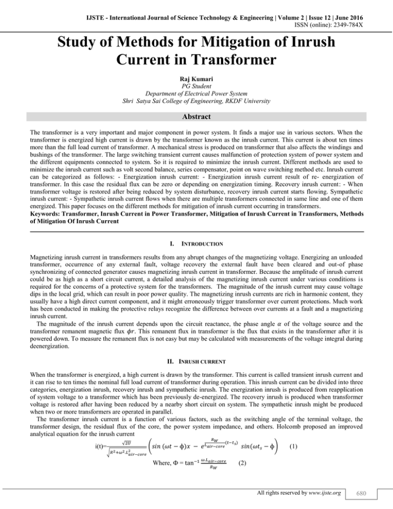
transformer design, the residual flux of the core, the power system impedance, and others. Holcomb proposed an improved
analytical equation for the inrush current
i(t)=
√2𝑈
√𝑅 2 +𝜔2 .𝐿2𝑎𝑖𝑟−𝑐𝑜𝑟𝑒
𝑅𝑊
(𝑠𝑖𝑛 (𝜔𝑡 − ф)𝑥 − 𝑒 𝐿𝑎𝑖𝑟−𝑐𝑜𝑟𝑒
Where, Ф = tan−1
(𝑡−𝑡𝑠 )
𝜔.𝐿𝑎𝑖𝑟−𝑐𝑜𝑟𝑒
𝑅𝑊
𝑠𝑖𝑛(𝜔𝑡𝑠 − ф)
(1)
(2)
All rights reserved by www.ijste.org
680
Study of Methods for Mitigation of Inrush Current in Transformer
(IJSTE/ Volume 2 / Issue 12 / 120)
Where U is the applied voltage; Lair-core is the winding resistance; is the air-core inductance of winding; and ts is the time
when the core begins to saturate (B (t) > Bs).
III. CAUSES OF INRUSH CURRENT
The main causes of transient inrush current are as moment of switching, residual flux. Transformer is highly inductive in nature.
Therefore current lags voltage by 90° as shown in fig.1.
Fig. 1: Transformer energization when voltage is at 0°
As shown in fig. 2, when transformer energized at 0 drgree the value of flux and current are at negative peak. Therefore the
flux increases at a higher rate and it becomes twice the value of flux in steady state condition. This increased value leads into
increment of the current ten to fifteen times the rated value.
Fig. 2: Transformer energization when voltage is at peak
As fig.2 when the transformer are energized at its positive peak value of instanteneous voltage i.e at 90° at this instant the
value of current and flux are zero. In order for the transformer to create an opposing voltage drop to balance against this applied
source voltage, a magnetic flux of rapidly increasing value must be generated. This results in rapid increase in winding current,
but actually not as rapidly as under normal conditions.
Fig. 3: Inrush Current
Thus no any surge value of current is formed when primary of transformer is energized at peak value of instantaneous voltage
IV. EFFECT OF INRUSH CURRENT
The inrush current affects whole power system. It mainly affects the transformer, protection system, equipments which are
connected to system and raises power quality issues.
All rights reserved by www.ijste.org
681
Study of Methods for Mitigation of Inrush Current in Transformer
(IJSTE/ Volume 2 / Issue 12 / 120)
Transformer
As the inrush current increases the temperature also increases by the theory of effect of negative temperature. So the temperature
of bushings and the windings increases.
Protection system
In protection system relay is important equipment. It detects the short circuit or abnormal conditions of system and isolates and
protects the system. The short circuit of transformer is always less than inrush current. It is hence sensed by relay system, so that
transformer is isolated from system which is normal. Thus inrush current causes malfunction of protective system. As the
protection system gets effected transformer gets isolated, there is interruption of system.
Power Quality
Due to the presence of harmonic content in inrush current causes wrong analysis with quipments. It also affects to heat rise of the
system.
V. EFFECT OF POINT ON WAVE SWITCHING METHOD ON INRUSH CURRENT
The switching time of circuit breaker is varied from 0° to 30°, 60° and 90° and various results are observed and analyzed. The
calculations for switching angle are given as belowTime duration for 50 cycles = 1000 msec
1 cycle =1000/50 = 20 msec
For switching at peak of voltage waveform with phase A,B and C 90° apartPhase A peak is at 90° = 0.005 sec
Phase A peak is at 90+120= 210° = 0.0116
Phase A peak is at 90 +240= 330° = 0.01833
Analysis done on inrush current of three phase transformer using MATLAB as shown in fig. 4
Fig. 4: Matlab Model
The switching time for the circuit breaker is changed from its parameter settings and we are able to have the following
observation table I.
Table – 1
Magnitude value of current and voltage
Switching Angle Imagnitude
Vmag
0°
1800
3.1*105
30°
2000
3.6*105
60°
1500
4*105
90°
820
4*105
All rights reserved by www.ijste.org
682
Study of Methods for Mitigation of Inrush Current in Transformer
(IJSTE/ Volume 2 / Issue 12 / 120)
Table 1 explains the magnitudes of current and voltage at different switching angles. It shows that the value of current at 0° is
too high and when the switching are provided at 90°and current value is reduced by using point on wave switching method to
lower value. Increasing of the switching angle will decrease the amplitude of inrush current.
Fig. 5: Effect of switching angle variation on the amplitude of inrush current
VI. EFFECT OF SOURCE RESISTANCE ON INRUSH CURRENT
In this case, the switching angle (θ) is 0°. The remanent flux (Br) is 0.826 Wb-coil. The effects of source resistance have been
considered by increasing Rt. fig. 5 shows the effect of source resistance on the amplitude of inrush current. From figure its seen
that as source resistance increases the amplitude of inrush current decreases. Also, it causes faster decay in the amplitude of
inrush current. Thus, it can be said that transformers display higher amount of inrush current that are located closer to the
generating plants that lasts much longer than transformer installed electrically away from generator.
The complexity of an algorithm is a function that gives the running time / or space in terms of the input size. In fact the time
and space used by the algorithm are two main measures that decide the efficiency of any algorithm.
Fig. 6: Effect of source resistance on the amplitude of inrush current
VII. EFFECT OF REMANENT FLUX ON INRUSH CURRENT
The effect of remanent flux on the peak current of the first cycle at different switching angles is shown in Fig. 7. As seen from
figure,
The peak current of first cycle has large change when the remanent flux varies. Also the results shows that switching at θ=90°
or Br=0 may not necessarily reduce the magnitude of inrush current. So an appropriate switching angle by considering remanent
flux should be selected for reducing inrush current.
All rights reserved by www.ijste.org
683
Study of Methods for Mitigation of Inrush Current in Transformer
(IJSTE/ Volume 2 / Issue 12 / 120)
Fig. 7: Effect of remanent flux on first cycle peak current
VIII. CONCLUSION
This paper focuses on various mitigation methods for inrush current in transformers. Current significantly reduces with point on
wave switching method. Increasing of the switching angle will decrease the inrush current amplitude. Results show that by
increasing switching angle will decrease the inrush current amplitude at a positive remanent flux or source resistance. The effect
of remanent flux on the first cycle peak current indicates that it has large changes when the remanent flux varies.
REFERENCES
[1]
[2]
[3]
[4]
[5]
[6]
[7]
Nilesh Deokar, Harpreet Singh, “ Mitigation and Analysis of Three Phase Transformer Magnetizing Inrush Current By Using Point on Wave Switching
Method”, IJETAE, Feb 2014.
M.Jamali, M. Mirzaie, ―Calculation & Analysis of transformer inrush current based on parameters of transformer & operating conditions‖, IEEE, 2011K.
Reena Moon, R.K.Dhatrak, “A Study of Effect of Magnetizing Inrush Current on Different Ratings Of Transformers” , IJAREIE, April 2014.
Sagar Bole, ―Mitigation of inrush current in transformer‖ IJITEE, Dec 2013.
H. John, J. Klaus, ―Elimination of transformer inrush current by controlled switching-part 1st: Theoretical considerations‖, IEEE Transactions on power
delivery, April 2001.
Jone H. Brunk, and Kalus J. Frohlich, Elimination of transformer inrush currents by controlled switching- Part- 1: theoretical consideration IEEE
transactions on power delivery, Vol. 16, No. 2, April 2001.
Jone H. Brunk, and Kalus J. Frohlich, Elimination of transformer inrush currents by controlled switching- Part- 2: Application and performance
consideration IEEE transactions on power delivery, Vol. 16, No. 2, April 2001.
All rights reserved by www.ijste.org
684

