Back-to-back capacitor bank switching is the energization of
advertisement
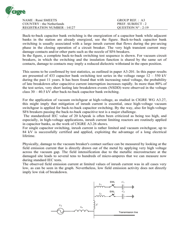
NAME : René SMEETS COUNTRY : the Netherlands REGISTRATION NUMBER : 14127 GROUP REF. : A3 PREF. SUBJECT : 2 QUESTION N° : 2-19 Back-to-back capacitor bank switching is the energization of a capacitor bank while adjacent banks in the station are already energized, see the figure. Back-to-back capacitor bank switching is usually associated with a large inrush current that flows during the pre-arcing phase in the closing operation of a circuit breaker. The very high transient current may damage contacts and/or other parts such as the nozzle of SF6 breakers. In the figure, a complete back-to-back switching test sequence is shown. For vacuum circuit breakers, in which the switching and the insulation function is shared by the same set of contacts, damage to contacts may imply a reduced dielectric withstand in the open position. This seems to be confirmed by test statistics, as outlined in paper A3-201. In this paper results are presented of 433 capacitor bank switching test series in the voltage range 12 – 550 kV during the past 11 years. It has been found that with increasing rated voltage, the probability of late breakdown after capacitive current interruption increases rapidly. In more than 80% of the test series, very short lasting late breakdown events (NSDD) were observed in the voltage class 30 – 40.5 kV after back-to-back capacitor bank switching. For the application of vacuum switchgear at high-voltage, as studied in CIGRE WG A3.27, this might imply that mitigation of inrush current is essential, once high-voltage vacuum switchgear is applied for back-to-back capacitor switching. By the way, also for high-voltage SF6 breakers passing the back-to-back capacitive test is a major challenge. The standardized IEC value of 20 kApeak is often been criticized as being too high, and especially, in high-voltage applications, inrush current limiting reactors are routinely applied in capacitor banks, as the work of CIGRE A3.26 shows. For single capacitor switching, inrush current is rather limited and vacuum switchgear, up to 84 kV is successfully certified and applied, exploiting the advantage of a long electrical lifetime. Physically, damage to the vacuum breaker's contact surface can be measured by looking at the field emission current that is directly drawn out of the metal by applying very high voltage across the vacuum gap. The field intensification due to the metallic microstructure at the damaged site leads to several tens to hundreds of micro-amperes that we can measure now during standard IEC tests. The observed field emission current at limited values of inrush current was in all cases very low, as can be seen in the graph. Nevertheless, low field emission activity does not directly imply low risk of breakdown. pre-strike contact touch current interruption 1 40 re-strike 40 load current 20 0.5 20 0 0 0 -0.5 -20 -1 100 -40 100 50 50 50 0 0 -20 -40 100 inrush current re-strike current 0 recovery voltage -50 -50 198 200 202 -100 100 150 200 250 300 350 400 450 500 550 600 -100 650 572 574 100 percentage of test-series with NSDD(s) -100 196 -50 single bank back‐to‐back 80 60 40 20 0 12‐15.5 kV 17.5‐29 kV 30‐40.5 kV rated voltage 20 inrush current 3.3 kApk 10 800 600 0 400 -10 200 -20 FE current 90 uA 0 0 20 2 4 inrush current 21 kApk 10 6 0 200 300 400 500 800 600 0 400 -10 200 -20 100 FE current 760 uA 0 0 2 4 6 0 100 200 300 400 500 576 578

