SATRON VG Flush Mount Pressure Transmitter
advertisement

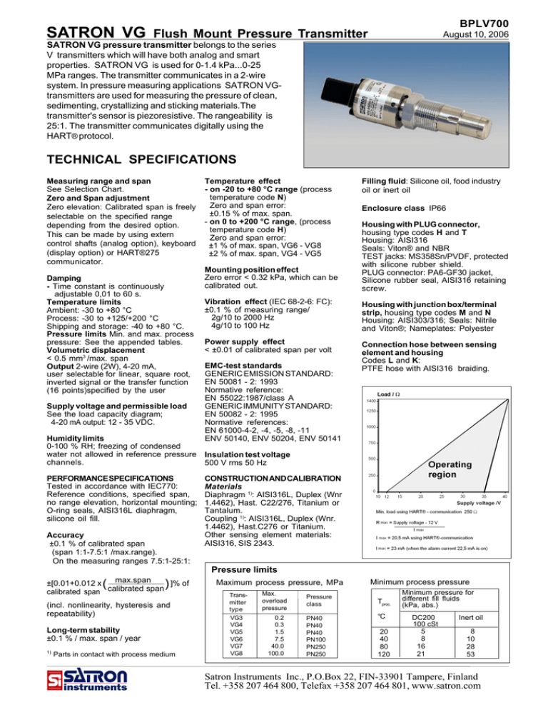
SATRON VG BPLV700 Flush Mount Pressure Transmitter August 10, 2006 SATRON VG pressure transmitter belongs to the series V transmitters which will have both analog and smart properties. SATRON VG is used for 0-1.4 kPa...0-25 MPa ranges. The transmitter communicates in a 2-wire system. In pressure measuring applications SATRON VGtransmitters are used for measuring the pressure of clean, sedimenting, crystallizing and sticking materials.The transmitter's sensor is piezoresistive. The rangeability is 25:1. The transmitter communicates digitally using the HART® protocol. TECHNICAL SPECIFICATIONS Measuring range and span See Selection Chart. Zero and Span adjustment Zero elevation: Calibrated span is freely selectable on the specified range depending from the desired option. This can be made by using extern control shafts (analog option), keyboard (display option) or HART®275 communicator. Damping - Time constant is continuously adjustable 0,01 to 60 s. Temperature limits Ambient: -30 to +80 °C Process: -30 to +125/+200 °C Shipping and storage: -40 to +80 °C. Pressure limits Min. and max. process pressure: See the appended tables. Volumetric displacement < 0.5 mm3 /max. span Output 2-wire (2W), 4-20 mA, user selectable for linear, square root, inverted signal or the transfer function (16 points)specified by the user Supply voltage and permissible load See the load capacity diagram; 4-20 mA output: 12 - 35 VDC. Temperature effect - on -20 to +80 °C range (process temperature code N) Zero and span error: ±0.15 % of max. span. - on 0 to +200 °C range, (process temperature code H) Zero and span error: ±1 % of max. span, VG6 - VG8 ±2 % of max. span, VG4 - VG5 Filling fluid: Silicone oil, food industry oil or inert oil Enclosure class IP66 Mounting position effect Zero error < 0.32 kPa, which can be calibrated out. Housing with PLUG connector, housing type codes H and T Housing: AISI316 Seals: Viton® and NBR TEST jacks: MS358Sn/PVDF, protected with silicone rubber shield. PLUG connector: PA6-GF30 jacket, Silicone rubber seal, AISI316 retaining screw. Vibration effect (IEC 68-2-6: FC): ±0.1 % of measuring range/ 2g/10 to 2000 Hz 4g/10 to 100 Hz Housing with junction box/terminal strip, housing type codes M and N Housing: AISI303/316; Seals: Nitrile and Viton®; Nameplates: Polyester Power supply effect < ±0.01 of calibrated span per volt Connection hose between sensing element and housing Codes L and K: PTFE hose with AISI316 braiding. EMC-test standards GENERIC EMISSION STANDARD: EN 50081 - 2: 1993 Normative reference: EN 55022:1987/class A GENERIC IMMUNITY STANDARD: EN 50082 - 2: 1995 Normative references: EN 61000-4-2, -4, -5, -8, -11 ENV 50140, ENV 50204, ENV 50141 Humidity limits 0-100 % RH; freezing of condensed water not allowed in reference pressure Insulation test voltage channels. 500 V rms 50 Hz PERFORMANCE SPECIFICATIONS Tested in accordance with IEC770: Reference conditions, specified span, no range elevation, horizontal mounting; O-ring seals, AISI316L diaphragm, silicone oil fill. Accuracy ±0.1 % of calibrated span (span 1:1-7.5:1 /max.range). On the measuring ranges 7.5:1-25:1: CONSTRUCTION AND CALIBRATION Materials Diaphragm 1): AISI316L, Duplex (Wnr 1.4462), Hast. C22/276, Titanium or Tantalum. Coupling 1): AISI316L, Duplex (Wnr. 1.4462), Hast.C276 or Titanium. Other sensing element materials: AISI316, SIS 2343. Pressure limits ±[0.01+0.012 x ( max.span ) ]% of calibrated span calibrated span (incl. nonlinearity, hysteresis and repeatability) Long-term stability ±0.1 % / max. span / year 1) Parts in contact with process medium Maximum process pressure, MPa Transmitter type VG3 VG4 VG5 VG6 VG7 VG8 Max. overload pressure 0.2 0.3 1.5 7.5 40.0 100.0 Pressure class PN40 PN40 PN40 PN100 PN250 PN250 Minimum process pressure Tproc. °C 20 40 80 120 Minimum pressure for different fill fluids (kPa, abs.) DC200 100 cSt 5 8 16 21 Inert oil 8 10 28 53 Satron Instruments Inc., P.O.Box 22, FIN-33901 Tampere, Finland Tel. +358 207 464 800, Telefax +358 207 464 801, www.satron.com BPLV700 SATRON VG Flush Mount Pressure Transmitter Calibration For customer-specified range with minimum damping. (If range is not specified, transmitter is calibrated for maximum range.) Process connections G1 connecting thread Process couplings: See Selection Chart and installation instructions or technical specification: Couplings for Transmitters G150. Electrical connections Housing with PLUG connector, H and T: PLUG connector, connector type DIN 43650 model AF; Pg9 gland for cable; wire gross-section 0.5 to 1.5 mm2. August 10, 2006 Weight Transmitter - with housing type H and T : 0.7 kg - with housing type M : 1.2 kg - with housing type N : 1.3 kg Housing with junction box/terminal strip, M and N : M20x1.5, 1/2-NPT inlet; screw terminals for 0.5 to 2.5 mm2 wires 1300354152 Dimensions (in mm) [Process temperature code H +40] [Process temperature code H, +40 mm] Option K Option L Remote electronics, connecting cable with protection hose, codes L and K Wiring Housing with PLUG-connector, codes H and T Wiring Wiring Housing with terminal strip, code M Housing with display, code N BPLV700 SATRON VG Flush Mount Pressure Transmitter Couplings Transmitter's process sealing AISI316L diaphragm, Viton O-ring (code 1) G1 ∅45 +0.2 +0.1 Three different options are available for the transmitter's process sealing: ∅25 +0.5 -0.2 +0.3 -0.5 70 ∅45.5 August 10, 2006 AISI316L diaphragm, PTFE O-ring (code 2) Standard coupling Material: AISI316 L or Hastelloy C AISI316L, CoNi-, Duplex, Hastelloy C276 or Tantalum diaphragm, metal/metal taper sealing (diaphragm on sealing face) (code 4) Special couplings: G1 hygienic coupling , M548101 G1/2A/G1 coupling, M546190 G1/2A/G1 coupling with venting, M860280 G1/2A/ G1 couplings with bracket: • G1/2A male, M546195 • G1/2 female, M550393 Flanges: Dimensions of flanged couplings, see the installation and setting-up instructions PASVE® mounting & service valve Process temperature limits, code H ® All PASVE types are also available with pneumatic actuator, flushing and limit switches. PASVE GF (NF) (Flange type) GP (NP) (Welded on pipe) Process temperature/°C GC (NC) (Welded on container) 200 150 55 66 Recommended application range (horizontal mounting) 41 100 Ø115 Ø70 ØD Ø127 L 50 6.5 R262 A 20 40 60 80 ambient temperature/°C S Hart® 1 PZ .5 Z D RUN 1 3 DN UP 60 Test 2 3 Keyboard : Use of RUN PZ D S Z DN UP selector switch : = working position = Process value zero = damping adjustment = Span adjustment = Zero adjustment = Down = Up Housing with PLUG-connector, housing code T Esc = = = Enter = Press Esc move back towards the top of the main menu. Use the UP arrow key to move up on the current menu level or to increase the selected parameter value. Use the DOWN arrow key to move down on the current menu level or to decrease the selected parameter value. Press ENTER to move to a lower level in a menu or to accept a command or parameter value. Housing with display, housing code N SATRON VG BPLV700 Flush Mount Pressure Transmitter August 10, 2006 Selection Chart Adjustability VG3 VG4 VG5 VG6 VGA6 VG7 VG8 Output Span, min 1.4 kPa (14 mbar) 4 kPa (40 mbar) 26.5 kPa (265 mbar) 0.145 MPa (1.45 bar ) 0.145 MPa 1.45 bar) 1 MPa (10 bar) 6,7 MPa (67 bar) Span, max 35 kPa (350 mbar) 100 kPa (1000 mbar) 500 kPa (5000 mbar) 3 MPa (30 bar) 3 MPa (30 bar) 15 MPa (150 bar) 25 MPa (250 bar) Measuring range - 35...+35 kPa (-350...350 mbar) -100...+100 kPa (-1000...1000 mbar) -100...+500 kPa (-1000...5000 mbar) -0.1...+3 MPa (-1...30 bar ) 0...+3 MPa (0...30 bar), abs. 0...+15 MPa (0...150 bar), abs. -0,1...+25 MPa (-1...250 bar) S 4-20mA DC/HART® -protocol Process seal 1 O-ring (Viton®) (**) Wetted materials Code Material 2 AISI316L 3 Hast. C 276 (*) (**) 5 Tantalum (*) (**) Fill fluid S Code 6 7 8 Silicon oil 2 O-ring (PTFE) (**) 4 metal/metal taper Diaphragm coating Code Material 9 gold/rhodium Y diamond Material Titanium (*) (**) CoNi-alloy (*) (not ranges 3-4) Duplex (Wnr 1.4462) (*) (**) G Inert oil A Food and beverage special oil (Neobee M20) Housing type H Housing with PLUG-connector, DIN43650, no display, inlet PG9 T Housing with PLUG-connector and with manual adjust, DIN43650, no display, inlet PG9 M Housing with junction box/terminal strip, no display, inlet M20x1,5 N Housing with junction box/terminal strip, with display, inlet M20x1,5 Explosion proof 0 No explosion proof classification Process temperature limits N -30 ... +125 °C Process coupling 0 No coupling G Standard coupling PASVE® 1 Ex ia IIC T4 (not Atex) H 0 ... +200 °C (*) (**) Material 2 AISI316L 3 Hast.C276 6 Titanium 8 Duplex mounting valve, specify separately in the order E Hygienic coupling Specify special couplings separately in the order Spesial size of electrical inlet N 1/2 NPT G Pg13.5 P PLUG-connector DIN43650 Special features Remote electronics (spesify only if housing connected with cable to sensing element) - connecting cable with protection hose L Hose protected with PTFE/AISI316 braiding, straight K Hose protected with PTFE/AISI316 braiding, angle of 90° Length of connection cable between sensing element and housing 2 2 m cable 3 3 m cable etc. (max. 10 m) Mounting parts for remote electronics for Ø 51 mm tube 0 No mounting parts 1 Documentation Calibration certificate Mounting parts AE English Installation and operating insructions IE English IF Finnish Material certificates 0 No material certificate MC1 Raw material certificate without appendixes, in accordance with SFS-EN 10204-2.1 (DIN 50049-2.1) standard MC2 Raw material certificate for wetted parts, in accordance with SFS-EN 10204-2.2 (DIN 50049-2.2) standard MC3 Raw material certificate for wetted parts, in accordance with SFS-EN 10204-3.1 B (DIN 50049-3.1 B) standard We reserve the right for technical modifications without prior notice. HART is the registered trademark of HART Communication Foundation. Pasve is the registered trademark of Satron Instruments Inc. Hastelloy is the registered trademark of Haynes International. Teflon is the registered trademark of E.I. du Pont de Nemours & Co. Viton is the registered trademark of DuPont Down Elastomer. (*) = only process seal code 4 (**) = not for range 3 MEETS THE COUNCIL OF THE EUROPEAN UNION DIRECTIVE 89/336/EEC FOR ELECTROMAGNETIC COMPATIBILITY REQUIREMENTS.


