Test Equipment, Power Supplies, and Noise
advertisement

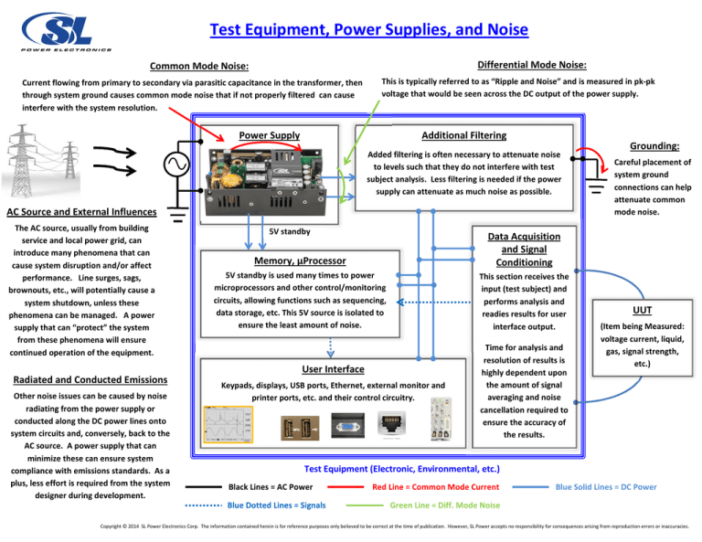
Test Equipment, Power Supplies, and Noise Differential Mode Noise: Common Mode Noise: Current flowing from primary to secondary via parasitic capacitance in the transformer, then through system ground causes common mode noise that if not properly filtered can cause interfere with the system resolution. This is typically referred to as “Ripple and Noise” and is measured in pk-pk voltage that would be seen across the DC output of the power supply. Power Supply Additional Filtering Added filtering is often necessary to attenuate noise to levels such that they do not interfere with test subject analysis. Less filtering is needed if the power supply can attenuate as much noise as possible. AC Source and External Influences The AC source, usually from building service and local power grid, can introduce many phenomena that can cause system disruption and/or affect performance. Line surges, sags, brownouts, etc., will potentially cause a system shutdown, unless these phenomena can be managed. A power supply that can “protect” the system from these phenomena will ensure continued operation of the equipment. Radiated and Conducted Emissions Other noise issues can be caused by noise radiating from the power supply or conducted along the DC power lines onto system circuits and, conversely, back to the AC source. A power supply that can minimize these can ensure system compliance with emissions standards. As a plus, less effort is required from the system designer during development. 5V standby Memory, µProcessor Data Acquisition and Signal Conditioning 5V standby is used many times to power microprocessors and other control/monitoring circuits, allowing functions such as sequencing, data storage, etc. This 5V source is isolated to ensure the least amount of noise. This section receives the input (test subject) and performs analysis and readies results for user interface output. User Interface Keypads, displays, USB ports, Ethernet, external monitor and printer ports, etc. and their control circuitry. Time for analysis and resolution of results is highly dependent upon the amount of signal averaging and noise cancellation required to ensure the accuracy of the results. Grounding: Careful placement of system ground connections can help attenuate common mode noise. UUT (Item being Measured: voltage current, liquid, gas, signal strength, etc.) Test Equipment (Electronic, Environmental, etc.) Black Lines = AC Power Blue Dotted Lines = Signals Red Line = Common Mode Current Blue Solid Lines = DC Power Green Line = Diff. Mode Noise Copyright © 2014 SL Power Electronics Corp. The information contained herein is for reference purposes only believed to be correct at the time of publication. However, SL Power accepts no responsibility for consequences arising from reproduction errors or inaccuracies.


