Steps to Balancing Wheatstone Bridges with a Honeywell Bridge
advertisement
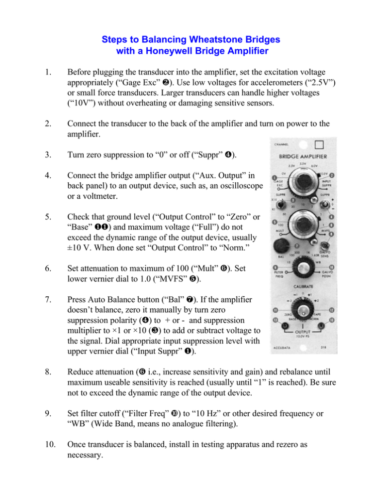
Steps to Balancing Wheatstone Bridges with a Honeywell Bridge Amplifier 1. Before plugging the transducer into the amplifier, set the excitation voltage appropriately (“Gage Exc” Ù). Use low voltages for accelerometers (“2.5V”) or small force transducers. Larger transducers can handle higher voltages (“10V”) without overheating or damaging sensitive sensors. 2. Connect the transducer to the back of the amplifier and turn on power to the amplifier. 3. Turn zero suppression to “0” or off (“Suppr” Û). 4. Connect the bridge amplifier output (“Aux. Output” in back panel) to an output device, such as, an oscilloscope or a voltmeter. 5. Check that ground level (“Output Control” to “Zero” or “Base” ØØ) and maximum voltage (“Full”) do not exceed the dynamic range of the output device, usually ±10 V. When done set “Output Control” to “Norm.” 6. Set attenuation to maximum of 100 (“Mult” Ý). Set lower vernier dial to 1.0 (“MVFS” Ü). 7. Press Auto Balance button (“Bal” Þ). If the amplifier doesn’t balance, zero it manually by turn zero suppression polarity (Û) to + or - and suppression multiplier to ×1 or ×10 (Ú) to add or subtract voltage to the signal. Dial appropriate input suppression level with upper vernier dial (“Input Suppr” Ø). 8. Reduce attenuation (Ý i.e., increase sensitivity and gain) and rebalance until maximum useable sensitivity is reached (usually until “1” is reached). Be sure not to exceed the dynamic range of the output device. 9. Set filter cutoff (“Filter Freq” á) to “10 Hz” or other desired frequency or “WB” (Wide Band, means no analogue filtering). 10. Once transducer is balanced, install in testing apparatus and rezero as necessary.


