Ideal Transformers
advertisement
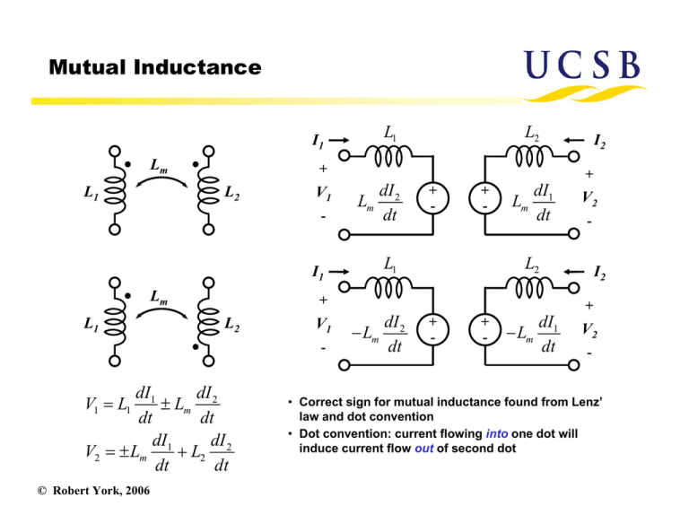
Mutual Inductance L1 I1 Lm L1 + L2 V1 - I1 Lm L1 L2 V1 dI1 dI ± Lm 2 dt dt dI dI V2 = ± Lm 1 + L2 2 dt dt © Robert York, 2006 I2 + Lm dI 2 dt + - + - L1 Lm dI1 dt V2 - L2 + - V1 = L1 L2 I2 + dI − Lm 2 dt + - + - − Lm dI1 dt V2 - • Correct sign for mutual inductance found from Lenz’ law and dot convention • Dot convention: current flowing into one dot will induce current flow out of second dot Transformers A transformer is just a special case where the mutual inductance is made as large as possible by allowing both coils to share the same flux This is usually achieved by winding them both on a common core of high permeability material (soft iron or ferrite materials) I1 I2 + + V1 V1 = jω L1 I1 + jω Lm I 2 V2 - - V2 = jω Lm I1 + jω L2 I 2 When there is no flux leakage, the mutual inductance is related to the primary and secondary inductances as Lm = L1 L2 For real transformers this can never be quite achieved, so we write Lm = k L1 L2 © Robert York, 2006 where 0 < k <1 coefficient of coupling Ideal Transformer 1:n I1 If both coils share the same flux, then Farady’s law gives: I2 + + V1 V2 - - As the permeability of the core increases, the relationship between the primary and secondary currents approaches a limiting value set by the turns ratio: V1 N1 1 = = V2 N 2 n I1 N2 ⇒ =n I2 N1 These two relationships define an ideal transformer. This is a fictitous element (note that µ→∞ implies infinite inductances so the impedance matrix is infinite) but a real transformer approximates this behavior. An idea transformer has the following useful property when one winding is terminated: I1 1:n I2 + + V1 V2 - - © Robert York, 2006 ZL V1 ( N1 / N 2 )V2 Z L Z in = = = 2 I1 ( N 2 / N1 ) I 2 n Transformer Equivalent Circuit Using the tee-equivalent for reciprocal networks, we find the following equivalent circuit for mutual inductances or transformers L1 − Lm L2 − Lm L1 ∝ N1 Lm L2 ∝ N 2 = n 2 L1 Lm = k L1 L2 = knL1 If desired, this circuit can be cascaded with an ideal 1:1 transformer to simulate the fact that a real transformer has electrically isolated ports © Robert York, 2006 Alternative equivalent circuit The following is also an identical equivalent that uses an ideal transformer to explicitly incorporate the turns ratio and isolation between ports L1 (1 − k 2 ) 1:n n= 2 k L1 L2 Lm ideal For good transformers, k is nearly 1, and this model also clearly shows why real transformers do not work at DC © Robert York, 2006


