MCM-4/MCM-8 Radiant Floor Control Module - Cube
advertisement
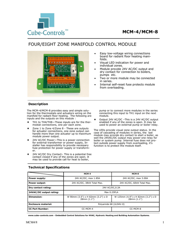
MCM-4/MCM-8 FOUR/EIGHT ZONE MANIFOLD CONTROL MODULE Easy low-voltage wiring connections board for radiant floor heating manifolds. Visual LED indication for power and individual zones. Module provide 24V AC/DC output and dry contact for connection to boilers, pumps etc. Two or more module may be connected in series. Internal self-reset fuse protects module from overloading. Description The MCM-4/MCM-8 provides easy and simple solution for the thermostats and actuators wiring on the manifold for radiant floor heating. The following are inputs and the outputs on this module : TH1 to TH4/TH8—These inputs are for the thermostat connections, one per each zone. Zone 1 to Zone 4/Zone 8 - These are outputs for actuator connections, one zone output can handle more than one actuator up to maximum module power output. 24V AC/DC Power—This is a power connection for external transformer or power supply, Installer has responsibility to provide necessary fuse protection for power supply or transformer. pump or to connect more modules in the series connecting this input to TH1 input on the next module. Output 24V AC/DC –This is a 24V AC/DC output enabled if any of the zones is open. It may be used to power an external pump or boiler relay. The LEDs provide visual zone output status. In the case of cascading of modules in series, the last module may provide dry contact to start a boiler, as well the 24VAC/DC output may power one relay for boiler or system pump. Internal fuse does not protect outside power supply from overloading, it's function is to protect the module itself. 24V AC/DC Dry Contact– This is a potential free contact closed if any of the zones are open. It may be used to provide call for heat to boiler, Technical Specifications MCM-4 MCM-8 Power supply: 24V AC/DC, max 1.85A 24V AC/DC, max 3.00A Power output: 24V AC/DC, 38VA Total Max. 24V AC/DC, 60VA Total Max. Dry contact rating: 24V AC/DC,0.2A 24VAC/DC output rating: Dimension: Max 0.25FLA W 90mm (3.5”) x H 82mm (3.2”) x D 28mm (1.1”) Enclosure material: CC Part Number: W 125mm (4.9”) x H 82mm (3.2”) x D 28mm (1.1”) Polyamide 68 (UL94V-0) CC-MCM-4 CC-MCM-8 www.cube-controls.com - Embedded Control Solutions for HVAC, Hydronic Heating and Building Automation Systems. MCM4/8 1 MCM-4/MCM-8 Connections Diagram for MCM-8 Installer has responsibility to provide a necessary fuse protection for the power supply or transformer used in an installation. www.cube-controls.com - Embedded Control Solutions for HVAC, Hydronic Heating and Building Automation Systems. MCM4/8 2 MCM-4/MCM-8 Connections Diagram for MCM-4 Installer has responsibility to provide a necessary fuse protection for the power supply or transformer used in an installation. www.cube-controls.com - Embedded Control Solutions for HVAC, Hydronic Heating and Building Automation Systems. MCM4/8 3 MCM-4/MCM-8 Cascading Connections Diagram 1. 2. 3. Cube-Controls Inc. keeps the right to change technical data in this data sheet without notice. All Cube-Controls products are not authorized for use as a critical component in any kind of control or monitoring application. CubeControls does not assume any liability arising out of our products use or malfunction .It is responsibility of the system designer to incorporate protection equipment appropriate to risk involved. Warranty period for replacement and repairs is 1 Year. www.cube-controls.com - Embedded Control Solutions for HVAC, Hydronic Heating and Building Automation Systems. MCM4/8 4
