SFP-LED Installation Instructions
advertisement
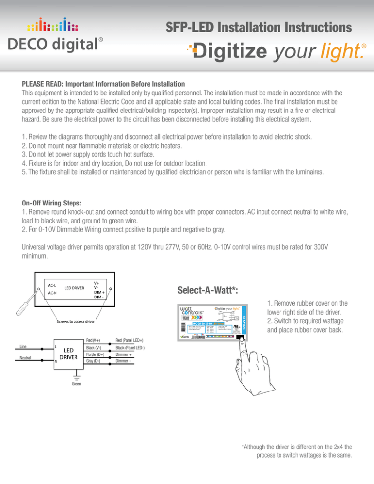
SFP-LED Installation Instructions PLEASE READ: Important Information Before Installation This equipment is intended to be installed only by qualified personnel. The installation must be made in accordance with the current edition to the National Electric Code and all applicable state and local building codes. The final installation must be approved by the appropriate qualified electrical/building inspector(s). Improper installation may result in a fire or electrical hazard. Be sure the electrical power to the circuit has been disconnected before installing this electrical system. 1. Review the diagrams thoroughly and disconnect all electrical power before installation to avoid electric shock. 2. Do not mount near flammable materials or electric heaters. 3. Do not let power supply cords touch hot surface. 4. Fixture is for indoor and dry location, Do not use for outdoor location. 5. The fixture shall be installed or maintenanced by qualified electrician or person who is familiar with the luminaires. On-Off Wiring Steps: 1. Remove round knock-out and connect conduit to wiring box with proper connectors. AC input connect neutral to white wire, load to black wire, and ground to green wire. 2. For 0-10V Dimmable Wiring connect positive to purple and negative to gray. Universal voltage driver permits operation at 120V thru 277V, 50 or 60Hz. 0-10V control wires must be rated for 300V minimum. Select-A-Watt*: 1. Remove rubber cover on the lower right side of the driver. 2. Switch to required wattage and place rubber cover back. Red (V+) Red (Panel LED+) Line Black (V-) Black (Panel LED-) Neutral Purple (D+) Gray (D-) Dimmer + Dimmer - Green *Although the driver is different on the 2x4 the process to switch wattages is the same. SFP-LED Installation Instructions Recessed Installation Steps: 1. Turn all power off before installation. 2. Connect driver to power source. 3. Insert LED Panel into T-Bar, face down. 4. For additional security use clips to secure to building structure. (Clip has hole for wire or cable support required by some local codes) Recessed Flange Kit Mounting Steps: 1. Use flat head screwdriver to slightly open up mounting holes on channels. 2. Insert L-bracket into mounting holes on channel by slightly tapping L-bracket with a hammer. (make sure not to bend L-bracket or channel) Pendant Mount Installation Steps: 1. Turn all power off before installation. 2. Attach wire grippers to back of panel. 3. Measure desirable wire length and then feed wire through each wire gripper. 4. Install universal bracket to J-Box (by others). 5. Feed power cable into junction box and hard wire the driver. 6. Secure canopy to the universal bracket mount via two screws. 7. Level the panel by fine tuning the length of wire by pressing the strain reliefs at the canopy and feed the wire in or out as necessary. Cut excess wire after final adjustment. Surface Mount Installation Steps: 1. IMPORTANT: Frame should be positioned over J-Box (by others) so as not to interfere with J-box on back of LED Panel. 2. Position 3 sides together making sure to use two sides with mounting holes. Mount 3 sided frame to ceiling making sure the power supply box does not interfere with driver box on back of panel. It is recommended that the power supply/j-box is mounted off-center of frame. 3. Make electrical connections to LED Panel according to local electrical codes. 4. Slide LED Panel into frame and attach 4th side of frame. (The J-Box or flex lead CANNOT be in the center location of the surface frame)

