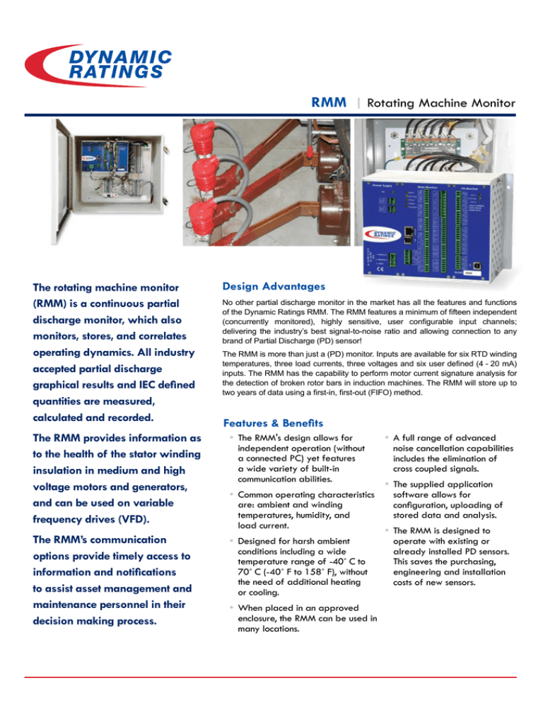
RMM | Rotating Machine Monitor
The rotating machine monitor
(RMM) is a continuous partial
discharge monitor, which also
monitors, stores, and correlates
operating dynamics. All industry
accepted partial discharge
graphical results and IEC defined
quantities are measured,
calculated and recorded.
Design Advantages
No other partial discharge monitor in the market has all the features and functions
of the Dynamic Ratings RMM. The RMM features a minimum of fifteen independent
(concurrently monitored), highly sensitive, user configurable input channels;
delivering the industry’s best signal-to-noise ratio and allowing connection to any
brand of Partial Discharge (PD) sensor!
The RMM is more than just a (PD) monitor. Inputs are available for six RTD winding
temperatures, three load currents, three voltages and six user defined (4 - 20 mA)
inputs. The RMM has the capability to perform motor current signature analysis for
the detection of broken rotor bars in induction machines. The RMM will store up to
two years of data using a first-in, first-out (FIFO) method.
Features & Benefits
The RMM provides information as
to the health of the stator winding
insulation in medium and high
voltage motors and generators,
and can be used on variable
frequency drives (VFD).
• The RMM's design allows for
independent operation (without
a connected PC) yet features
a wide variety of built-in
communication abilities.
The RMM’s communication
options provide timely access to
information and notifications
to assist asset management and
maintenance personnel in their
decision making process.
• Designed for harsh ambient
conditions including a wide
temperature range of -40˚ C to
70˚ C (-40˚ F to 158˚ F), without
the need of additional heating
or cooling.
• Common operating characteristics
are: ambient and winding
temperatures, humidity, and
load current.
• When placed in an approved
enclosure, the RMM can be used in
many locations.
• A full range of advanced
noise cancellation capabilities
includes the elimination of
cross coupled signals.
• The supplied application
software allows for
configuration, uploading of
stored data and analysis.
• The RMM is designed to
operate with existing or
already installed PD sensors.
This saves the purchasing,
engineering and installation
costs of new sensors.
RMM | Rotating Machine Monitor
Applications
• Hydro & Turbo Generators
• Motors, Including VFD's
• Connected Bus Duct or Cables
A Wide Variety of Connectivity
and Communication Solutions
Communications ports include Ethernet, USB and RS-485
with a standard communication protocol using ModBus.
DNP-3 is available upon request. Dry relay contacts are also
available to indicate monitor health and alarm conditions.
Equipment Failures
Motors and Generators are key assets in most utility and
industrial applications. Studies from the IEEE and EPRI
(Electric Power Research Institute) show that up to 37% of forced
outages are caused by failures in the stator insulation system.
Bearings
& Vibration
50%
Stator
37%
Rotor
Winding
10%
RMM monitors Turbos, Motors and Hydros
Other
Electrical origin of HV motor failure
Motor Failures
Source: CIGRE Motor Failure Survey WG A1.19
3%
Compatible with Partial Discharge Sensors
Source: CIGRE Motor Failure Survey WG A1.19
4%
2%
Sensor Connecon box
11%
32%
Winding Insulaon
and short circuits
GPCS
Cables
12%
Capacitor
Main terminal connecons
Over current
12%
RFCT
Heang resistances
27%
Phase unbalance
RMM
RTD Module
Hydro Generator
Hydro Generator
Winding
Temperature
Winding
Temperature
Load Current
Load Current
RTD-PD Module
RTD-PD Module
Isolation Joint
Isolation Joint
Software Package
The supplied application software is intended to run
on PC's with Microsoft WindowsTM software. Our RMM
application software is a versatile product supporting
Dynamic Ratings portable and continuous insulation
monitoring systems that may be
found on generators, motors,
switchgear, cables, bus duct,
and transformers. The software
allows the user to configure the
instrumentation, download
and store the data and
provides tools for data presentation and analysis.
Graphic Results
Test results can be presented
in all industry accepted formats:
• 2D Phase Resolved
• 3D Phase Resolved
• Polar Phase Resolved
• Trend
2D Phase Resolved
• Pulse Height Distribution
The software allows for the trending of all
standard quantities of magnitudes, pulse counts,
PD Intensity as well as operating dynamics. Multiple
channels can be presented on the same screen for
easy comparison and analysis.
3D Phase Resolved
Polar Phase Resolved
Iso-Phase Bus Duct
Iso-Phase Bus Duct
Isolation Joint
Isolation Joint
RMM
RMM
Cabinet
Cabinet
N
N
Top OilTop Oil
Temperature
Temperature
Pulse
Polarity
Pulse
Polarity
GSU
GSU
Time
of of
Flight
Time
Flight
PRODUCT
PRODUCTKEY
KEY
Ambient
Temperature
Ambient
Temperature
Bushing
Sensor
Bushing
Sensor
Load
Load
DTM Current Current
DTM
Cabinet Cabinet
RFCT
RFCT
Coupling
Capacitor
Coupling
Capacitor
Humidity
Sensor
Humidity
Sensor
Equipment
Equipment
Temperature
Temperature
Ground
Path
Ground
Path
Current
Sensor
- GPCS
Current
Sensor
- GPCS
Total)
Rogowski
Coil
(3 (3
Total)
Rogowski
Coil
Case Study
Customer Avoids Costly Generator Rewind
& Extends Asset Useful Life
A West Coast Hydro producer has been performing Partial Discharge
measurements on a periodic basis for over 10 years. Their measuring
equipment and technology had become obsolete. During their quest
to upgrade their technology, it was decided to go with a cost effective
continuous monitoring system from Dynamic Ratings.
The cost of implementing continuous PD monitoring on two generators was
less than purchasing a new portable analyser. Savings were achieved by
utilising the existing coupling capacitors from another vendor. Their original
investment was not lost.
Since the coupling capacitors alone only provide 10-15% winding coverage,
the system was upgraded to reuse six existing RTDs as additional PD
sensors, thus expanding the coverage. The RMM is now detecting PD that is
occurring deeper in the winding, which was not being detected previously.
Using both of these complementary sensors, the customer is
receiving more information—therefore making better decisions
as to the health of the equipment.
In conjunction with
monitoring the generators,
the customer decided to
monitor the Isolated Phase
Bus Duct and the Generator
Step-up Transformer
(GSU) by installing the
Dynamic Ratings Diagnostic
Transformer Monitor (DTM).
PD From coupling capacitors
PD From RTDs not detected
at the coupling capacitors
PD From RTDs not detected
at the coupling capacitors
This complete system
monitors the generator, bus duct, and transformer. The customer has
further reduced their off-line maintenance costs for these critical assets.
Trend
Pulse Height Distribution
RMM | Rotating Machine Monitor
SPECIFICATIONS
PD Channels:
Dynamic Range:
Power Frequency Phase Resolution:
Power Requirement:
Internal Memory:
Magnitude Windows:
Measurement Frequency Bandwidth:
Temperature Range:
User Interface:
15 channels per module with concurrent data acquisition
70 dB, 3 mV to 10 V, with no gain adjustment
7.5˚
90 - 264 VAC line voltage (47 to 63Hz), 100 to 300 VDC
8 MB
32
1 MHz to 20 MHz
- 40˚ C to 70˚ C / - 40˚ F to 158˚ F
PC
RMM — ordering information
Base System1
RMM Base System: H, T, or M (select one of the following)
H = Hydro Generator, Monitor.............................................................................. H
T = Turbo Generator, Monitor................................................................................ T
M = Motor Monitor................................................................................................... M
-
-
Optional Modules
Partial Discharge (PD) Optional Modules 1 or 2 (select one of the following)
1 = (One), 15 Channel Partial Discharge (PD) Monitoring Module........................... 1
2 = (Two), 15 Channel Partial Discharge (PD) Monitoring Modules.......................... 2
-
Packaging Options2,3,4 Packaging Options: S, P, or E (select one of the following)
S = Stand-alone Monitor............................................................................................................... S
P = Panel2,4 Mounted Monitor...................................................................................................... P
E = Monitor is Mounted in a NEMA 4x Enclosure3,4................................................................. E
Communication
Protocols
Notes
1
2
3
4
Communication Options: D or M (select one of the following)
D = DNP 3.0 Communications ................................................................................................................. D
M = Modbus Communications ................................................................................................................. M
All base systems include (1) AuxCT current transformer, (1) AmbH ambient humidity sensor and (1) AmbT ambient temperature sensor.
Panel size may vary to accommodate base system selection. Consult the factory with questions.
Enclosure size may vary to accommodate base system options and enclosure type.
Packaging options P and E include the monitor mounted with all terminals wired out to terminal blocks.
Microsoft WindowsTM is a registered trademark of Microsoft Corporation
SENSORS and Accessories
The products above are compatible with industry sensors, including Dynamic Ratings; Coupling Capacitors,
rtd-pd Sensing Module, Ground Path Current Sensor and Radio-Frequency Current Transformer Sensors.
Contact us for a “Sensors & Accessories for Partial Discharge (PD) Monitoring Systems” product catalogue.
Contact your sales representative
for application assistance or pricing.
Asia / Africa / United Kingdom
+61 3 9574 7722
sales.asia@dynamicratings.com
Americas / Europe / India / Middle East
+1 262 746-1230
sales.us@dynamicratings.com
www.dynamicratings.com
©2013 Dynamic Ratings Subject to change without notice. All rights reserved. RMM 130604 ASIA


