Quasi-Cyclic LDPC Codes for the Magnetic Recording
advertisement
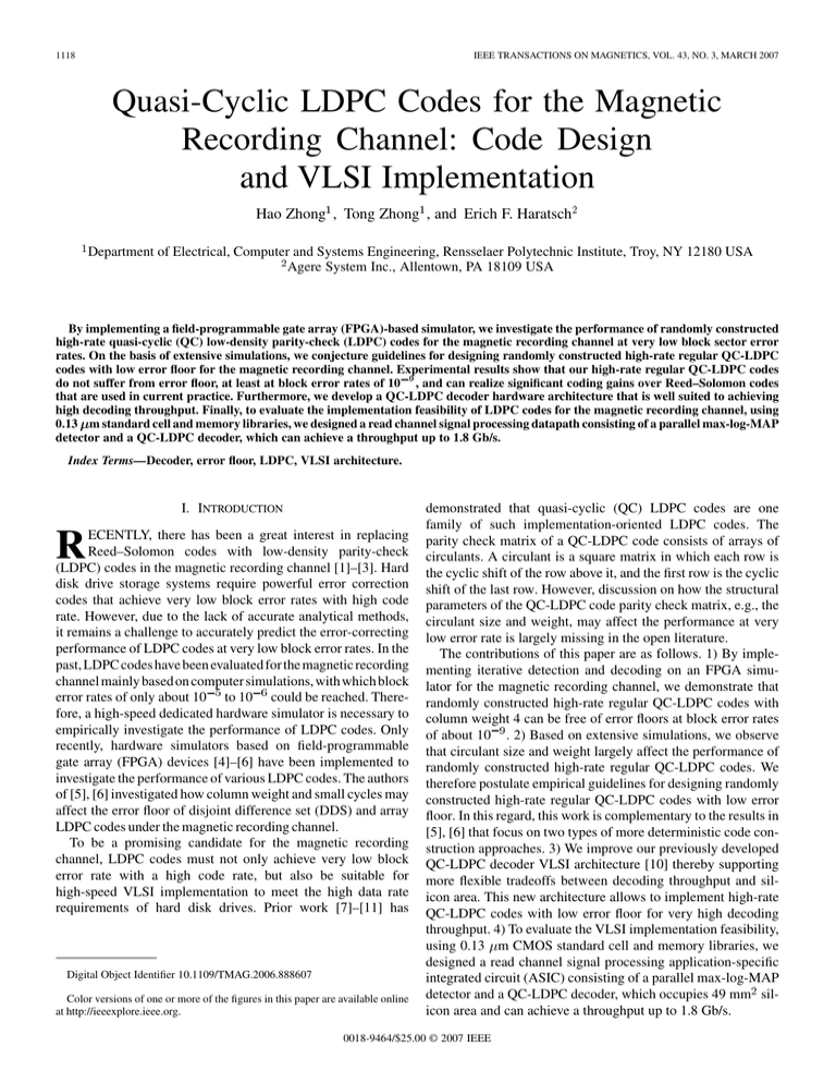
1118 IEEE TRANSACTIONS ON MAGNETICS, VOL. 43, NO. 3, MARCH 2007 Quasi-Cyclic LDPC Codes for the Magnetic Recording Channel: Code Design and VLSI Implementation Hao Zhong1 , Tong Zhong1 , and Erich F. Haratsch2 Department of Electrical, Computer and Systems Engineering, Rensselaer Polytechnic Institute, Troy, NY 12180 USA Agere System Inc., Allentown, PA 18109 USA By implementing a field-programmable gate array (FPGA)-based simulator, we investigate the performance of randomly constructed high-rate quasi-cyclic (QC) low-density parity-check (LDPC) codes for the magnetic recording channel at very low block sector error rates. On the basis of extensive simulations, we conjecture guidelines for designing randomly constructed high-rate regular QC-LDPC codes with low error floor for the magnetic recording channel. Experimental results show that our high-rate regular QC-LDPC codes do not suffer from error floor, at least at block error rates of 10 9 , and can realize significant coding gains over Reed–Solomon codes that are used in current practice. Furthermore, we develop a QC-LDPC decoder hardware architecture that is well suited to achieving high decoding throughput. Finally, to evaluate the implementation feasibility of LDPC codes for the magnetic recording channel, using 0.13 m standard cell and memory libraries, we designed a read channel signal processing datapath consisting of a parallel max-log-MAP detector and a QC-LDPC decoder, which can achieve a throughput up to 1.8 Gb/s. Index Terms—Decoder, error floor, LDPC, VLSI architecture. I. INTRODUCTION ECENTLY, there has been a great interest in replacing Reed–Solomon codes with low-density parity-check (LDPC) codes in the magnetic recording channel [1]–[3]. Hard disk drive storage systems require powerful error correction codes that achieve very low block error rates with high code rate. However, due to the lack of accurate analytical methods, it remains a challenge to accurately predict the error-correcting performance of LDPC codes at very low block error rates. In the past, LDPC codes have been evaluated for the magnetic recording channel mainly based on computer simulations, with which block error rates of only about 10 to 10 could be reached. Therefore, a high-speed dedicated hardware simulator is necessary to empirically investigate the performance of LDPC codes. Only recently, hardware simulators based on field-programmable gate array (FPGA) devices [4]–[6] have been implemented to investigate the performance of various LDPC codes. The authors of [5], [6] investigated how column weight and small cycles may affect the error floor of disjoint difference set (DDS) and array LDPC codes under the magnetic recording channel. To be a promising candidate for the magnetic recording channel, LDPC codes must not only achieve very low block error rate with a high code rate, but also be suitable for high-speed VLSI implementation to meet the high data rate requirements of hard disk drives. Prior work [7]–[11] has R Digital Object Identifier 10.1109/TMAG.2006.888607 Color versions of one or more of the figures in this paper are available online at http://ieeexplore.ieee.org. demonstrated that quasi-cyclic (QC) LDPC codes are one family of such implementation-oriented LDPC codes. The parity check matrix of a QC-LDPC code consists of arrays of circulants. A circulant is a square matrix in which each row is the cyclic shift of the row above it, and the first row is the cyclic shift of the last row. However, discussion on how the structural parameters of the QC-LDPC code parity check matrix, e.g., the circulant size and weight, may affect the performance at very low error rate is largely missing in the open literature. The contributions of this paper are as follows. 1) By implementing iterative detection and decoding on an FPGA simulator for the magnetic recording channel, we demonstrate that randomly constructed high-rate regular QC-LDPC codes with column weight 4 can be free of error floors at block error rates of about 10 . 2) Based on extensive simulations, we observe that circulant size and weight largely affect the performance of randomly constructed high-rate regular QC-LDPC codes. We therefore postulate empirical guidelines for designing randomly constructed high-rate regular QC-LDPC codes with low error floor. In this regard, this work is complementary to the results in [5], [6] that focus on two types of more deterministic code construction approaches. 3) We improve our previously developed QC-LDPC decoder VLSI architecture [10] thereby supporting more flexible tradeoffs between decoding throughput and silicon area. This new architecture allows to implement high-rate QC-LDPC codes with low error floor for very high decoding throughput. 4) To evaluate the VLSI implementation feasibility, using 0.13 m CMOS standard cell and memory libraries, we designed a read channel signal processing application-specific integrated circuit (ASIC) consisting of a parallel max-log-MAP detector and a QC-LDPC decoder, which occupies 49 mm silicon area and can achieve a throughput up to 1.8 Gb/s. 0018-9464/$25.00 © 2007 IEEE ZHONG et al.: QUASI-CYCLIC LDPC CODES FOR THE MAGNETIC RECORDING CHANNEL Fig. 1. FPGA-based simulator system. The remainder of this paper is organized as follows. Section II describes the read channel iterative detection and decoding FPGA simulator platform implementation. Section III discusses the construction of low error floor random QC-LDPC codes and presents the simulation results for randomly constructed regular high-rate QC-LDPC codes with different code lengths and rates. Section IV presents an improved decoder architecture that supports flexible tradeoffs between throughput and silicon area. Section V presents the ASIC implementation results, and Section VI draws the conclusions. II. FPGA SIMULATOR FOR THE READ CHANNEL WITH ITERATIVE DETECTION AND DECODING Fig. 1 shows the diagram of the iterative detection and decoding simulator that consists of two Altera Stratix-II 180 FPGA devices.1 The first FPGA device models the magnetic recording channel as extended partial response class 4 (EPR4) signal in presence of additive white Gaussian noise (AWGN). Although realistic read channel can be much more complex than the channel model used throughout this work (i.e., ideal EPR4 plus pure AWGN noise), such ideal and widely used channel model may dramatically increase the simulation speed while ensuring good fidelity. The AWGN generator is designed based on the quantized version of the Box–Muller method [12]. It generates a random sample with Gaussian distribution (zero ) using two random samples mean and standard deviation and uniformly distributed between [0, 1] as follows: where and An array of 64-bit linear feedback shift registers is used to and . The functions generate the random samples and are implemented using lookup tables. The calculated sample is scaled according to the signal-to-noise ratio (SNR) at the output of the AWGN generator. To achieve high-speed simulation, 16 independent AWGN generators are implemented to feed the successive signal detector with a wide data bandwidth. The second FPGA device implements the iterative detection and decoding datapath consisting of a parallel max-log-MAP detector and a QC-LDPC decoder. To support high throughput, the parallel max-log-MAP detector contains multiple identical sub-detectors operating in parallel on different portions of the 1As the currently largest FPGA on the market, the Altera Stratix-II 180 FPGA device contains 186 576 equivalent 4-input lookup tables (LUTs) and 9 Mb of on-chip memory. 1119 incoming data sequence, where each sub-detector employs the well-known sliding window method [13]. The QC-LDPC decoder is implemented based on the partially parallel decoder architecture presented in [10]. Following the turbo principle, the soft extrinsic information from the QC-LDPC detector output may be fed back to the max-log-MAP detector to improve the performance. One cycle of soft information exchange between the detector and decoder is referred to as one global iteration. As shown in Fig. 1, the PC host provides randomly generated codewords for simulation. Due to the speed mismatch between the FPGA simulation and the data transfer between the simulator and PC host, each random codeword is used for 10 rounds of FPGA simulations. The finite precision parameters of this simulator are outlined as follows. a) The output of the AWGN generator is 6 bits. b) In the max-log-MAP detector, the path metrics are 9 bits, and the detector soft output is 6 bits. c) In the QC-LDPC decoder, the internal decoding messages and soft outputs are 6 bits. The number of global iterations between the detector and decoder can be adjusted to realize different tradeoffs between performance and simulation throughput. If we set the number of global iterations to 4 (i.e., the decoder feeds back soft output to the detector by up to 4 times) and the number of internal decoding iterations to 4 (i.e., for each global iteration, the decoder carries out 4 internal decoding iterations), this simulator can reach sector error rates down to 10 within 1–2 days. III. SIMULATION RESULTS AND DISCUSSION The parity check matrix of a QC-LDPC code can be written as .. . where each sub-matrix is a circulant over GF(2). Notice that a zero matrix is a special case of circulants with the weight 0. In this work, we focus on randomly constructed high-rate regular QC-LDPC codes, where all the nonzero circulants have the same weight. Given the structural parameters, in, column weight , and nonzero circulant weight cluding , we randomly construct the parity check matrix subject to the constraint that there are no cycles of degree 4. In all the parity check matrices (for code rate no less than 8/9) we have ever constructed, at most there are only one or two redundant rows. . Hence, the code rate can be approximated as Leveraging the FPGA simulator, we investigated how those code parity check matrix structural parameters affect the performance of high-rate QC-LDPC codes, as discussed below. All the simulated block error rates presented in the following were obtained under the condition that at least 10 erroneous sectors are captured. For the simulation results presented below, we configured the simulator as follows: i) the decoder may feed back soft information to the detector up to four times and ii) for each global iteration, the QC-LDPC decoder carries out four internal decoding iterations. 1120 Fig. 2. Block error rate performance for random QC-LDPC codes with column weights 3 and 4. Because the computational complexity for LDPC decoding is proportional to the parity check matrix column weight , QC-LDPC codes with small values of should be preferred. Therefore, we first investigated high-rate QC-LDPC codes with column weight 3. Nevertheless, our simulations suggest that badly suffer from error floor, as QC-LDPC codes with have shown in Fig. 2, whereas QC-LDPC codes with much better resilience to error floor. Therefore, we focused on high-rate QC-LDPC codes with column weight 4 and investigated how the other parity check matrix structural parameters, including circulant size and nonzero circulant weight , affect the performance. In this regard, we constructed several rate-8/9 QC-LDPC codes with two different code lengths, i.e., 4608 and 8640. For the code of length 4608, we considered four different sets of parity check (i.e., matrix structural parameters, including: 1) and ) and equals either 0 or 1; 2) (i.e., and ) and for all circulants; 3) (i.e., and ) and for all circulants; and 4) (i.e., and ) and for all circulants. For the code length of 8640, we considered three different (i.e., and sets of parameters, including: i) ) and equals either 0 or 1; ii) (i.e., and ) and for all circulants; iii) (i.e., and ) and for all circulants. Fig. 3 shows the simulation results for these randomly constructed QC-LDPC and , and codes. The length-4608 code with suffer from error floor, while length-8640 code with an error floor does not show up for the other codes in the block error rate region that can be observed by this FPGA simulator. The above results suggest that the circulant size should not be too small relative to the size of the code parity check matrix. On the other hand, if the circulant size is so large that the circulant weight has to be larger than 2, e.g., the length-4608 code with and , the the performance tends to degrade and is seriously subject to error floor. IEEE TRANSACTIONS ON MAGNETICS, VOL. 43, NO. 3, MARCH 2007 Fig. 3. Block error rate performance under difference code lengths and structural parameters. Fig. 4. Block error rate performance under different code lengths and rates. From the above simulation results, we conjecture the following guidelines for designing randomly constructed high-rate QC-LDPC codes with column weight 4 and low error floors for the magnetic recording channel: i) make the circulant size relatively large and ii) keep the circulant weight at either 1 or 2. Accordingly, we constructed several high-rate QC-LDPC codes with different code lengths and rates, for which the simulated performance is shown in Fig. 4. All the codes have column weight 4 and circulant weight 2, while the code rates vary from to . Although the performance curve slopes vary for different code lengths and code rates, none of these codes are explicitly subject to error floor at the block error rate of 10 . We note that, although iterative detection and decoding can achieve very good error correcting performance, it demands much higher silicon overhead and/or leads to significant throughput degradation compared with noniterative detection ZHONG et al.: QUASI-CYCLIC LDPC CODES FOR THE MAGNETIC RECORDING CHANNEL 1121 error rates for RS codes are calculated based on the code minimum distance and the simulated symbol error probability at the output of a hard-output Viterbi detector. IV. QC-LDPC DECODER DESIGN FOR HIGH THROUGHPUT Fig. 5. Block error rate performance of QC-LPDC codes with and without iterative detection/decoding and their competing RS codes (note that the RS codes in (a) and (b) are constructed under GF(2 ) and GF(2 ), respectively. and decoding (i.e., the decoder does not feed back soft information to the detector at all). Therefore, it is of interest to investigate the potential performance degradation if no global iteration is performed. Fig. 5(a) and (b) shows the simulated codes with code lengths of 4608 performance of rateand 8640 , respectively. For the scenarios without global iterations, the LDPC decoder carries out up to 16 internal decoding iterations. The simulation results show that the scheme without global iterations incurs about 1 dB loss compared with their counterparts with global iterations (notice that, in the scenarios with global iterations, the decoder feeds back the soft information to the detector up to 4 times). Furthermore, for the purpose of comparison, we also plot the Reed–Solomon (RS) block error rate curves when ratecodes with comparable code lengths are being used. The block As discussed above, in order to achieve a low error floor, the circulant size (i.e., the value for ) of randomly constructed high-rate QC-LDPC codes should be relatively large. The QC-LDPC decoder architectures presented in [9], [10] are suitable for high-speed decoding due to their simple datapath and fixed interconnect structure. However, the decoding parallelism in these decoders is inversely proportional to , i.e., the computations of each group of variable or check nodes are mapped onto a single hardware processing unit in a time-division multiplexed manner. Large values for will directly reduce the achievable throughput of such decoders. To solve this problem, we propose an improved decoder architecture that can map the computations for each group of (where is divisible by and is defined as the ratio ) variable or check nodes onto a single hardware processing unit, leading to an times improvement of the decoding parallelism. Fig. 6(a) shows the decoder architecture for a QC-LDPC code parity check matrix. It contains groups with a of check node computation units (CNUs) and groups of variable node computation units (VNUs), where each group contains CNUs or VNUs. Each CNU (VUN) performs the computations associated with consecutive rows (columns) in the parity check matrix in a time-division multiplexed mode. All the decoding messages and channel messages are stored in a memory fabric, as shown in Fig. 6(a). Each decoding iteration takes clock cycles. • During the first clock cycles, the decoder works in check node processing mode, i.e., carrying out the computations associated with all the check nodes; • During the second clock cycles, the decoder works in variable node processing mode, i.e., carrying out the computations associated with all the variable nodes. The real challenge in the decoder design is how to design the memory fabric and interconnect between the memory fabric and CNU/VNU array in such a way that all the messages required for the same variable or check node computation are sent to the same VNU or CNU at the same clock cycle. In the following, we present our solution to tackle this issue. The memory fabric mainly contains arrays of decoding message memory blocks (DMMBs) and channel message memory blocks (CMMBs). Recall that represents the weight of nonzero circulants. All the decoding messages associated with one nonzero circulant are stored in DMMBs. Notice that each nonzero circulant can be considered as a sum of permutation matrices. Each DMMB stores the decoding messages associated with the 1’s in each permutation matrix. The address space of each DMMB is , and each address location stores decoding messages. Let denote the decoding messages sorted in ascending order by the column index of the corresponding 1’s in the permutation matrix. At the th address location, DMMB stores the decoding messages . For nonzero circulant , the corresponding DMMB group has the architecture as shown in Fig. 6(b), which is explained below. 1122 IEEE TRANSACTIONS ON MAGNETICS, VOL. 43, NO. 3, MARCH 2007 Fig. 6 (a) General decoder architecture, and (b) storage of the decoding messages associated with nonzero circulant Each DMMB is a dual-port memory and has one port always configured for read and another one always configured for write. The read address of each DMMB is generated by a represent the column indices of binary counter. Let . In the nonzero entries in the first row of the circulant each decoding iteration, the state of the binary counter associated with is initialized as at the beginning of the check node processing mode and initialized as 0 at the beginning of the variable node processing mode. The write address is simply a delayed version of the read address depending on how many pipeline stages are inserted in the datapath between the DMMB memory data output and input ports. The barrel shifter is a combinational circuit that can rotate the input by any number of bits in a single operation. The are configured to robarrel shifters associated with tate decoding messages. As illustrated in Fig. 6(b), the DMMB group associated with circulant connects with the th group of CNUs and th group of VNUs. Example: Given a circulant with size and weight , let column indices of the two nonzero entries in the first row of the circulant to be 39 and 67, respectively. Assume the parallelism of VNU/CNU group is . Thus, the decoding messages associated with this circulant are stored in two DMMBs in which each address contains four decoding messages . The relevant messages passing is as follows. 1) At every clock cycle during check node processing mode, the CNUs connected to the DMMBs read four variable-to-check messages from each of DMMBs with initial address 39 and 67 , respectively. Then the check-to-variable messages are calculated by CNUs and written back to the DMMBs. The messages read by or written to the CNUs pass through barrel shifters and rotate position for the first set decoding messages and positions for the second set decoding messages. 2) At every clock cycle during variable node processing mode, the VNUs connected to the DMMBs read four check-to-variable messages from each DMMB with initial address as 0. Then the variable-to-check messages are calculated by VNUs and written back to the DMMBs. The memory fabric contains CMMB blocks, each of which stores the channel messages for each group of consecutive variable nodes. Each CMMB is a single-port memory with the address space of . Each memory location stores channel messages. The storage pattern of the channel messages in one CMMB is the same as the pattern in DMMB: Let H . denote the channel messages sorted in ascending order by the column index, then each CMMB stores channel messages at the th address location. Since the channel messages are only used in variable node processing mode, the CMMBs only send the data to the corresponding VNU groups. The read address of each CMMB is generated by a binary counter that is initialized to 0 at the beginning of the variable node processing mode. V. ASIC IMPLEMENTATION Using 0.13 m CMOS standard cell and memory libraries, we designed a detection/decoding ASIC consisting of a parallel max-log-MAP detector and a QC-LDPC decoder. The QC-LDPC code has a code length of 4608 and code rate of 8/9. The code parity check matrix contains 4 36 circulants, where each circulant has the size of 128 and weight of 1. The detector and decoder follow the same finite precision configurations as those in the FPGA simulator (as described in Section II). The detector contains nine identical sub-detectors that execute sliding window detection in parallel, where the length of the sliding window is 16. The QC-LDPC decoder contains four CNU groups and 36 VNU groups, and each CNU (VNU) group contains eight CNUs (VNUs). This ASIC chip is designed using Chartered 0.13 m CMOS standard cell and SRAM libraries with eight metal layers. Synopsys tools are used throughout the design hierarchy: VCS-MX is used for functional simulation and post-simulation, Design Compiler is used for logic synthesis, optimization, and scan insertion, Formality is used for formal verification, Astro is used for floor planning, placement, and routing, and PrimeTime is used for pre/post-layout static timing analysis (STA). The layout plot of the entire design is shown in Fig. 7. It consumes about 2 million gates and 320 memory macros. All the memory macros are placed in rings around the perimeter of the core and occupy a total area of 15.6 mm . The die occupies 49 mm with 50% utilization efficiency. To increase the clock frequency, the datapath is deeply pipelined and the retiming technique is used to balance the pipeline stages. Based on the post-layout timing analysis with worst case libraries, the clock frequency can be set up to 225 MHz (at the power supply of 1.2 V), with the critical path located in memory access. The decoding throughput is calculated as follows: For a QC-LDPC code with parity check matrix , let denote the clock frequency, represent the decoding parallelism ZHONG et al.: QUASI-CYCLIC LDPC CODES FOR THE MAGNETIC RECORDING CHANNEL 1123 weight 4 can achieve error-floor-free performance for sector . Based on extensive FPGA error rates down to at least simulations, we postulated empirical guidelines for designing randomly constructed high-rate QC-LDPC codes with low error floors. Moreover, by improving published decoder architectures, we presented a new decoder architecture that is better suited to achieving high throughput for high rate QC-LDPC codes. Finally, a detector/decoder ASIC design has been presented to demonstrate the silicon implementation feasibility of LDPC-based read channel signal processing. ACKNOWLEDGMENT This work was supported by SRC Contract No. 2004-HJ1192. Fig. 7. ASIC layout plot. TABLE I IMPLEMENTATION METRICS improvement factor, and represent the maximum decoding iteration number, we have the worst case decoding throughput as . Notice that channel message memory initialization does not incur decoding throughput overhead since we use two sets of channel message memory blocks (i.e., when one set is being used for current decoding, another one is being initialized by the next input data block). In this design, we use the parameters as MHz, , , and and , which leads to 1.8 Gb/s. This is the worst case throughput that can be guaranteed at low SNRs. At higher SNRs, because of the on-line parity-check for early decoding termination, the average number of decoding iterations can be less or much less than 16, leading to a potentially higher average decoding throughput. For the case with global iteration, the throughput will reduce to about 360 Mb/s if the decoder feeds back soft information to the detector four times for four global iterations and carries out four internal iterations each time. The estimated power consumption is 1.7 W at 1.2 V power supply, 25 C temperature, and 225 MHz clock. The implementation metrics are summarized in Table I. VI. CONCLUSION Using an FPGA-based simulator, we empirically evaluated high-rate QC-LDPC codes for the magnetic recording channel at low block error rates. We demonstrated that randomly constructed high-rate regular QC-LDPC codes with column REFERENCES [1] A. Dholakia, E. Eleftheriou, T. Mittelholzer, and M. P. C. Fossorier, “Capacity-approaching codes: Can they be applied to the magnetic recording channel?,” IEEE Commun. Mag., vol. 42, no. 2, pp. 122–130, Feb. 2004. [2] Y.-H. Kwon, M.-K. Oh, and D.-J. Park, “A new LDPC decoding algorithm aided by segmented cyclic redundancy checks for magnetic recording channels,” IEEE Trans. Magn., vol. 41, no. 7, pp. 2318–2320, Jul. 2005. [3] T. Kanaoka and T. Morita, “Structured LDPC codes with reversed MTR/ECC for magnetic recording channels,” IEEE Trans. Magn., vol. 42, no. 10, pp. 2561–2563, Oct. 2006. [4] D. Divsalar, S. Dolinar, J. Thorpe, and C. Jones, “Constructing LDPC codes from simple loop-free encoding modules,” in Proc. IEEE Int. Conf. Communications, May 2005, pp. 658–662. [5] L. Sun, H. Song, and B. V. K. V. Kumar, “Proc. of IEEE International Conference on Acoustics, Speech, and Signal Processing,” in Proc. IEEE Int. Conf. Communications, Mar. 2005, pp. 1101–1104. [6] L. Sun, H. Song, B. V. K. V. Kumar, and Z. Keirn, “Field-programmable gate-array-based investigation of the error floor of low-density parity check codes for magnetic recording channels,” IEEE Trans. Magn., vol. 41, no. 10, pp. 2983–2985, Oct. 2005. [7] M. M. Mansour and N. R. Shanbhag, “Architecture-aware low-density parity-check codes,” in IEEE Int. Symp. Circuits and Systems (ISCAS), May 2003, pp. 57–60. [8] D. E. Hocevar, “Architecture-aware low-density parity-check codes,” in Proc. IEEE Int. Conf. Communications, 2003, pp. 2708–2712. [9] J. K.-S. Lee, B. Lee, J. Thorpe, K. Andrews, S. Dolinar, and J. Hamkins, “A scalable architecture of a structured LDPC decoder,” in Int. Symp. Information Theory, Jul. 2003. [10] H. Zhong and T. Zhang, “Block-LDPC: A practical LDPC coding system design approach,” IEEE Trans. Circuits Syst. I, vol. 52, no. 4, pp. 766–775, Apr. 2005. [11] Z. Li, L. Chen, S. Lin, W. Fong, and P.-S. Yeh, “Efficient encoding of quasi-cyclic low-density parity-check codes,” IEEE Trans. Commun., vol. 54, no. 1, pp. 71–81, Jan. 2006. [12] E. W. Weisstein, “From MathWorld—A Wolfram Web Resource.” [Online]. Available: http://mathworld.wolfram.com/Box-MullerTransformation.html [13] A. J. Viterbi, “An intuitive justification and a simplified implementation of the MAP decoder for convolutional codes,” IEEE J. Sel. Areas Commun., vol. 16, no. 2, pp. 260–264, Feb. 1998. Manuscript received March 3, 2006; revised November 17, 2006. Corresponding author: H. Zhong (e-mail: hzhong@agere.com).

