(EE 101: RC circuit (time domain))
advertisement
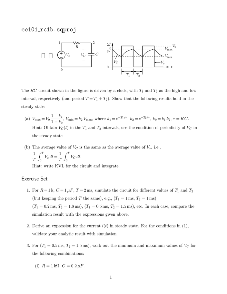
1 2 R Vs VC C VC , Vs ee101 rc1b.sqproj V0 Vmax Vmin VC 0 Vs t 0 T1 T2 The RC circuit shown in the figure is driven by a clock, with T1 and T2 as the high and low interval, respectively (and period T = T1 + T2 ). Show that the following results hold in the steady state: 1 − k1 , Vmin = k2 Vmax , where k1 = e−T1 /τ , k2 = e−T2 /τ , k0 = k1 k2 , τ = R C. 1 − k0 Hint: Obtain VC (t) in the T1 and T2 intervals, use the condition of periodicity of VC in (a) Vmax = V0 the steady state. (b) The average value of VC is the same as the average value of Vs . i.e., 1 ZT 1 ZT Vs dt = VC dt. T 0 T 0 Hint: write KVL for the circuit and integrate. Exercise Set 1. For R = 1 k, C = 1 µF , T = 2 ms, simulate the circuit for different values of T1 and T2 (but keeping the period T the same), e.g., (T1 = 1 ms, T2 = 1 ms), (T1 = 0.2 ms, T2 = 1.8 ms), (T1 = 0.5 ms, T2 = 1.5 ms), etc. In each case, compare the simulation result with the expressions given above. 2. Derive an expression for the current i(t) in steady state. For the conditions in (1), validate your analytic result with simulation. 3. For (T1 = 0.5 ms, T2 = 1.5 ms), work out the minimum and maximum values of VC for the following combinations: (i) R = 1 kΩ, C = 0.2 µF . 1 (ii) R = 0.2 kΩ, C = 1 µF . (iii) R = 0.2 kΩ, C = 0.2 µF . (iv) R = 5 kΩ, C = 5 µF . Compare your values with simulation results. 4. Repeat for the current i(t). 2


![Km 1 Vm [S] 1) v = = v vs. [S] - Hyperbolic 2) Lineweaver Burk](http://s2.studylib.net/store/data/018724715_1-069561ef6a33d2749e373bad86f80405-300x300.png)

