Engineer-to-Engineer Note
a
EE-108
Technical notes on using Analog Devices DSPs, processors and development tools
Visit our Web resources http://www.analog.com/ee-notes and http://www.analog.com/processors or
e-mail processor.support@analog.com or processor.tools.support@analog.com for technical support.
Managing Multiple Applications in a Single EPROM for SHARC®
Processors
Contributed by Benno Kusstatscher and Jeyanthi Jegadeesan
Introduction
This EE-Note describes how multiple (up to six)
VisualDSP++® executables are stored in a single
EPROM. A simple modified boot loader
determines at boot time, which executable is to
be loaded. This approach is applicable for both
multiprocessor systems and single processor
systems. For a single processor system, the
processor can be booted from any of the multiple
applications stored in the flash. In a
multiprocessor system, any of the multiple
applications can be booted in any of the
processors connected on the external bus. The
modified boot kernel will decide which
application is loaded on which processor during
boot time.
Example code is provided for the ADSP-21161N
processor in the associated .ZIP file. The
example code is tested on the ADSP-21161N
EZ-KIT Lite® board with the VisualDSP++ 4.5
(November 2006 update) development tools.
How Does it Work?
VisualDSP++ loader supports a booting scheme
whereby a cluster of up to six processors can be
booted from a single EPROM.
The generated hexadecimal file contains the boot
loader and the boot images for the processors.
Furthermore, a table that is included contains the
EPROM offset address of the executables. After
Rev 2 – March 6, 2007
reset, the identical boot loader will be loaded into
all the SHARC® processors of the cluster. The
original boot loader first determines the ID of the
processor it is running on. From the offset table,
it obtains the address where the corresponding
data is stored in the EPROM. Finally, the boot
loader boots the application as in a singleprocessor scheme.
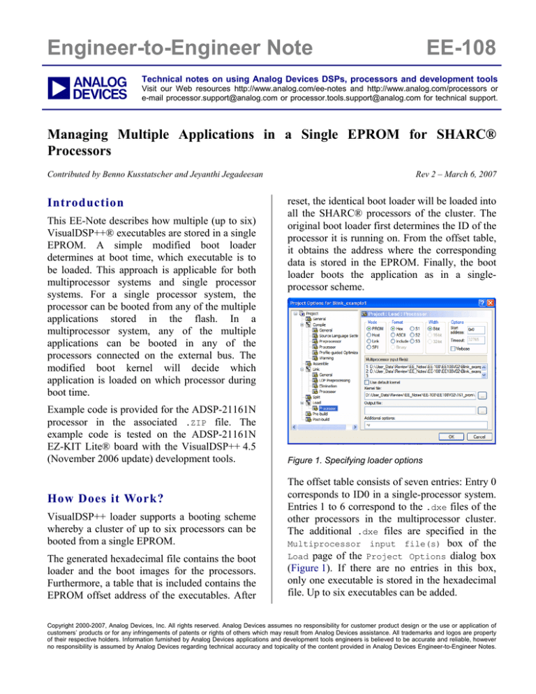
Figure 1. Specifying loader options
The offset table consists of seven entries: Entry 0
corresponds to ID0 in a single-processor system.
Entries 1 to 6 correspond to the .dxe files of the
other processors in the multiprocessor cluster.
The additional .dxe files are specified in the
Multiprocessor input file(s) box of the
Load page of the Project Options dialog box
(Figure 1). If there are no entries in this box,
only one executable is stored in the hexadecimal
file. Up to six executables can be added.
Copyright 2000-2007, Analog Devices, Inc. All rights reserved. Analog Devices assumes no responsibility for customer product design or the use or application of
customers’ products or for any infringements of patents or rights of others which may result from Analog Devices assistance. All trademarks and logos are property
of their respective holders. Information furnished by Analog Devices applications and development tools engineers is believed to be accurate and reliable, however
no responsibility is assumed by Analog Devices regarding technical accuracy and topicality of the content provided in Analog Devices Engineer-to-Engineer Notes.
a
We will take advantage of this feature and use
the Multiprocessor input file(s) box to
group multiple executables in an EPROM. But
now something else (rather than the processor
ID) determines which application will be loaded.
So the original boot loader has to be modified
slightly.
Modifying the boot loader normally requires an
in-depth understanding of the boot scenario.
Refer to Tips and Tricks on SHARC EPROM and
Host Boot Loader (EE-56)[5] for more
information. In this case, this is not necessary.
First, you should create a new project (let’s call
it multi_loader) to rebuild the boot loader.
Then, copy the original source file
(060_prom.asm or 065L_prom.asm) and the
corresponding
Linker
Description
File
(060_ldr.ldf
or
065L_ldr.ldf)
from
<install_path>\21k\ldr
into
your
project
directory. You can use the 060 files for all
ADSP-2106x processors except for ADSP21065L processors. The original 060_ldr.ldf
file selects the ADSP-21062 processor. Feel free
to change the type.
Search in the original source file for the
instructions that determines the processor’s ID:
R0=DM(SYSTAT);
R0=FEXT R0 BY 8:3;
Without caring about the rest of the code, the two
code lines above determine the ID stored in R0.
The content of R0 determines which executable
is to be booted. Now, these two instructions will
be replaced by any others. For example, R0 might
be controlled by a jumper connected to the flag
pins. Two issues must be taken into account:
R0 must get a value between 1 and 6
The maximal length of the boot loader must
not exceed 256 instructions
The following example is for the ADSP-21061
processor’s EZ-KIT Lite board. Normally, this
loader will boot program #1, but if the FLAG1
button is pushed during reset, program #2 will be
loaded instead.
R0=1;
IF NOT FLAG1_IN R0=R0+1;
That is all! The next example is for the ADSP21065L processor’s EZ-KIT Lite board. Booting
is controlled by push buttons FLAG2, FLAG1, and
FLAG0.
R0=ASTAT;
R0=FEXT R0 BY 16:3;
R0=R0+1;
R7=6;
R0=R0 CLIP BY R7;
When all the push buttons are released after
reset, program #1 is loaded. Program #2 is
loaded when the FLAG0 button is pushed, and so
on.
Since you may modify R0 any way you like,
many scenarios become possible. Instead of
simply checking the flag pins, you can set up the
SPORT or a Link Port to receive the number of
the application to be booted.
R0=0x_____;
DM(RDIV0)=R0;
R0=0x_____;
DM(SRCTL0)=R0;
R0=DM(RX0);
Additionally, this technique can also be used to
load the same executable into more (or all)
SHARC processors in a cluster. Of course, you
can do that using the original boot loader, but
then you have to store the same application more
times in the EPROM. Just use the following
instruction
R0=1;
or even
R0=0;
when the Multiprocessor input file(s) box
is not used.
Furthermore, you can load program #1 into
processors ID2, ID4, and ID6 and load
program #2 into processors ID1, ID3, and ID5.
R7=0x01;
R0=R0 AND R7;
R0=R0+1;
You might even combine the ID with a jumper
value.
Managing Multiple Applications in a Single EPROM for SHARC® Processors (EE-108)
Page 2 of 4
a
ADSP-21161N Example Code
The .ZIP file associated with this EE-Note
includes the project files for the modified PROM
boot kernel and two blink LED applications.
kernel option and select the path of the
modified PROM boot kernel files available with
the EE-Note for the kernel file.
Blink example 1 toggles FLAGS4-6 and blink
example 2 toggles FLAGS7-9 on the ADSP21161N EZ-KIT Lite board. The PROM boot
kernel is modified to boot the application, based
on the FLAG2 switch on the board. During reset,
if the FLAG2 switch is pressed, blink example 1 is
booted; otherwise, example 2 is booted.
Test Setup
Perform the following procedure to test this
approach:
1. Test the applications
Build the modified PROM boot kernel project
files included with this EE-Note. Individually
test both blink LED examples on the ADSP21161N EZ-KIT Lite board.
2. Create the loader file
To create the combined loader file for both
applications, specify Loader file as the project
target Type in the Project Options dialog box
as shown in Figure 2.
Figure 3. Specifying multiprocessor input files
Click the "Rebuild All" button to generate the
.ldr file.
3. Program the application in flash
Using the VisualDSP++ Flash Programmer
utility, program the combined loader file into the
flash.
4. Boot the applications
After programming the flash, close the
VisualDSP++ debug session and press the reset
button on the EZ-KIT Lite board. By default,
blink example 2 is booted; when the FLAG2
button is pressed during reset, blink example 1 is
booted. Note that the boot configuration on the
ADSP-21161N EZ-KIT Lite board must be
configured for EPROM boot.
Summary
Figure 2. Specifying a Loader file as output
This EE-Note describes how to modify the boot
kernel to manage up to six applications from a
single EPROM. Example code is provided for
the ADSP-21161N EZ-KIT Lite board.
From the Load:
Processor page of the
Project Options dialog box (Figure 3), select
both .dxe files. Deselect the Use default boot
Managing Multiple Applications in a Single EPROM for SHARC® Processors (EE-108)
Page 3 of 4
a
References
[1] ADSP-2106x SHARC Processor User’s Manual. Rev 2.1, March 2004. Analog Devices, Inc.
[2] ADSP-21065L SHARC Processor User’s Manual. Rev 2.0, July 2003. Analog Devices, Inc.
[3] ADSP-21160 SHARC Processor Hardware Reference. Rev 3.0, November 2003. Analog Devices, Inc.
[4] ADSP-21161 SHARC Processor Hardware Reference. Rev 4.0, February 2005. Analog Devices, Inc.
[5] Tips and Tricks on SHARC EPROM and Host Boot Loader (EE-56). Rev 3, March 2007, Analog Devices Inc.
Document History
Revision
Description
Rev 2 – March 6, 2007
by Jeyanthi Jegadeesan
Generalized the document for ADSP-2106x and ADSP-2116x SHARC processors.
Changed title from Storing Multiple Applications in a Single Boot EPROM to
Managing Multiple Applications in a Single EPROM for SHARC Processors.
Rev 1 – March 23, 2000
by Benno Kusstatscher
Initial release for ADSP-2106x processors.
Managing Multiple Applications in a Single EPROM for SHARC® Processors (EE-108)
Page 4 of 4


